Lock for multiple locking at outer casing or door of cabinet or side wall

A technology of housing and locking components, which is applied in the direction of building locks, building fastening devices, buildings, etc., to achieve the effect of increasing protection

Inactive Publication Date: 2007-11-21
DIRAK DIETER RAMSAUER KONSTRUKTIONSELEMENTE GMBH & CO KG +1
View PDF2 Cites 2 Cited by
  • Summary
  • Abstract
  • Description
  • Claims
  • Application Information

AI Technical Summary

Problems solved by technology

Disadvantage is the space required for the rod articulation

Method used


Image

  • Lock for multiple locking at outer casing or door of cabinet or side wall
  • Lock for multiple locking at outer casing or door of cabinet or side wall
  • Lock for multiple locking at outer casing or door of cabinet or side wall

Examples


Embodiment Construction

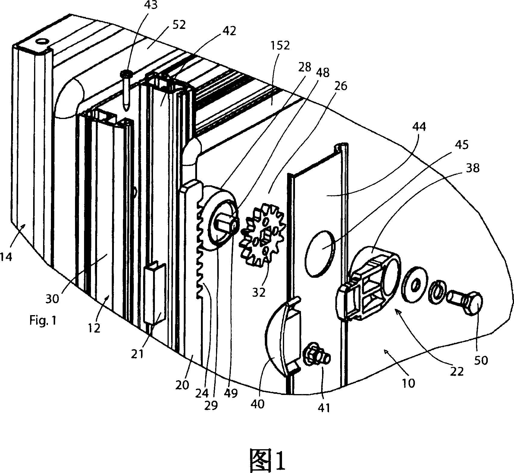
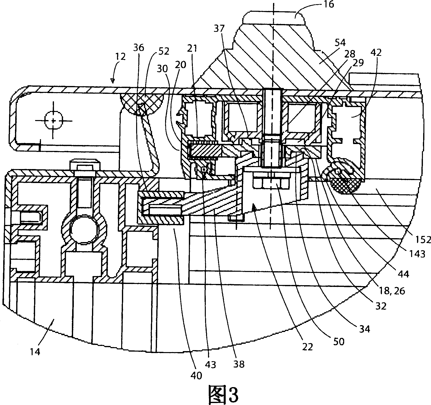
[0029] 1 shows an expanded perspective view of a lock 10 for multiple locking of a door 12 of a cabinet 14 with a drive gear 18 torsionally rigidly connected to an operating element installed in the door 12, such as a handle bar 16 of FIG. , the driving gear meshes with a toothed locking bar 20 installed in the door in an axially movable manner, and a locking element 22 that can keep rotating and is connected with the locking bar 20 is provided in the door. A driven gear 26 which is torsionally rigidly connected to the locking elements 22 and which meshes with the teeth 24 of the locking lever 20 is always used to connect the locking lever 20 to each locking element 22 and is rotatably held on the door 12, See bearing with key 28.

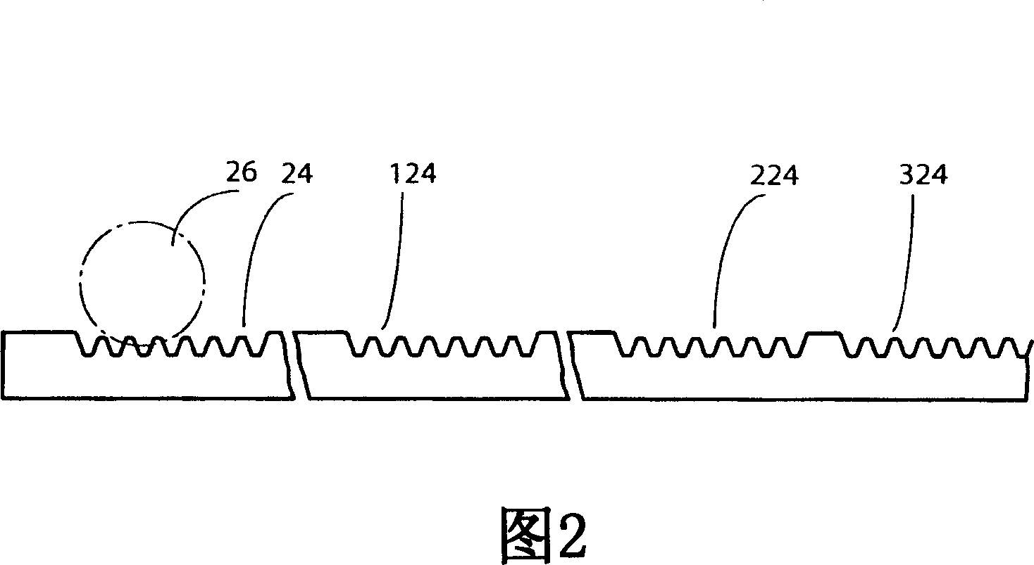
[0030] As shown in FIG. 2, the teeth 24 of the rack 20 can be composed in whole or in part of the tooth portions 24, 124, 224, 234, etc., wherein one of such portions, such as the portion 324, meshes with the drive gear 18, while the rest 24 , 124...


PUM


Abstract

To solve a problem that conventionally, a user having a semiconductor memory such as an IC card where image data are stored and battery might forget to carry it. A digital camera data transmission stand is used which acquires image data from a digital camera and transmits the acquired data. Further, a digital camera data transmission stand is used which has a function of charging a battery of the digital camera, in addition to the former stand. The latter digital camera data transmission stand can be fixed on a stand irrespective of the size of the digital camera. Even if the digital camera is of any type, image data can be transmitted, and the battery can be charged.

Description

technical field [0001] The present invention relates to a lock for multiple locking of doors or wall parts in housings or cabinets by means of lockable operating elements such as handle levers, in particular for outdoor situations, including in combination with door-mounted The operating element twists a rigidly connected drive gear that meshes with an axially displaceable locking bar mounted in the door and that is toothed on at least one side and that is rotatably or torsionally held in the door and connected to the locking bar one or more locking elements. Background technique [0002] A lock arrangement for such a cabinet door is known from US 4,631,937, wherein the locking process is realized by a lockable operating element such as a handle bar, comprising a drive gear connected torsionally rigidly to the operating element mounted behind the door, the driving gear Engages with an axially movable and toothed locking bar mounted in the door, but does not show the appeara...

Claims


Application Information

Patent Timeline
Patent Type & Authority Applications(China)
IPC IPC(8): E05C9/18E05C9/02E05B15/16
CPCE05C9/021E05C9/1875E05B15/1614Y10T292/0843
Inventor 迪特尔·拉姆绍尔赖纳·布雷特施奈德拉尔斯·加拉施
Owner DIRAK DIETER RAMSAUER KONSTRUKTIONSELEMENTE GMBH & CO KG
Why Eureka
Try Eureka