
Electronic sphygmomanometer

An electronic sphygmomanometer and pressure technology, applied in the direction of cardiac catheterization, etc., can solve problems such as fluctuations, inability to distinguish, and inability to repeatedly determine blood pressure

Inactive Publication Date: 2007-11-28
王超文
View PDF0 Cites 12 Cited by
  • Summary
  • Abstract
  • Description
  • Claims
  • Application Information

AI Technical Summary

Problems solved by technology

[0005] Therefore, the same blood pressure, measured by electronic sphygmomanometers from different manufacturers, will give different results. The existing electronic sphygmomanometers determine systolic blood pressure and diastolic blood pressure each time, only the final numerical results. Users can use simple numerical results. It is impossible to compare electronic sphygmomanometers from different manufacturers, let alone tell which electronic sphygmomanometer's results are more in line with your real blood pressure situation
[0006] When the user uses the same electronic blood pressure measurement at different times, different blood pressure results will be obtained, and there may be large fluctuations. The user cannot tell whether it is the result caused by the real blood pressure fluctuation or the blood pressure measurement. caused by the error
[0007] From the above descriptions, it can be seen that the existing electronic sphygmomanometers cannot compare blood pressure measurements between different sphygmomanometers, different individuals, and different measurement times when measuring blood pressure, cannot distinguish the accuracy of the measured blood pressure, and cannot compare the measured blood pressure. repeated determination of blood pressure

Method used


Image

  • Electronic sphygmomanometer
  • Electronic sphygmomanometer
  • Electronic sphygmomanometer

Examples


Embodiment 1

[0060] After a complete pressurization and slow deflation of an electronic sphygmomanometer in the present invention, after the static pressure in the cuff and the pulse wave fluctuation signal are sampled by AD, the pulse wave rising edge fluctuation amplitude, falling edge fluctuation amplitude, and pulse wave fluctuation amplitude are obtained. The fluctuation range values ​​are shown in Figure 10.

[0061] Column D in Fig. 10 is the value of pulse wave fluctuation amplitude, and the maximum value can be obtained as 71, which is recorded as Dmax=71.

[0062] All values ​​of the pulse wave fluctuation amplitude are normalized by Dmax.

[0063] En=(Dn / Dmax)*100%

[0064] In the formula:

[0065] Dn is the value of pulse wave fluctuation amplitude, n=1.2 N is the ordinal value of sampling.

[0066] En is the normalized value.

[0067] For the convenience of calculation and drawing, enlarge En by 100 times, En=En*100.

[0068] The calculated En is the first axis, and the s...

Embodiment 2

[0072] After a complete pressurization and slow deflation of an electronic sphygmomanometer in the present invention, after the static pressure in the cuff and the pulse wave fluctuation signal are sampled by AD, the pulse wave rising edge fluctuation amplitude, falling edge fluctuation amplitude, and pulse wave fluctuation amplitude are obtained. The fluctuation range values ​​are shown in Figure 10.

[0073] Column D in Fig. 10 is the value of pulse wave fluctuation amplitude, and the minimum value can be obtained as 18, which is recorded as Dmin=18.

[0074] All values ​​of the pulse wave fluctuation amplitude are normalized by Dmin.

[0075] Fn=(Dn / Dmin)*100%

[0076] In the formula:

[0077] Dn is the value of pulse wave fluctuation amplitude, n=1.2 N is the ordinal value of sampling.

[0078] Fn is the normalized value.

[0079] For the convenience of calculation and drawing, Fn is enlarged by 100 times, Fn=Fn*100.

[0080] Take the calculated Fn as the first axis, ...

Embodiment 3

[0084] After a complete pressurization and slow deflation of an electronic sphygmomanometer in the present invention, after the static pressure in the cuff and the pulse wave fluctuation signal are sampled by AD, the pulse wave rising edge fluctuation amplitude, falling edge fluctuation amplitude, and pulse wave fluctuation amplitude are obtained. The fluctuation range values ​​are shown in Figure 10.

[0085] Column D in Fig. 10 is the value of pulse wave fluctuation amplitude, and the average value is 44.6, which is recorded as Daverage=44.6.

[0086] All values ​​of the pulse wave fluctuation amplitude are normalized by Daverage.

[0087] Gn=(Dn / Daverage)*100%

[0088] In the formula:

[0089] Dn is the value of pulse wave fluctuation amplitude, n=1.2 N is the ordinal value of sampling.

[0090] Gn is the normalized value.

[0091] For the convenience of calculation and drawing, Gn is enlarged 100 times, Gn=Gn*100.

[0092] The calculated Gn is the first axis, and the ...


PUM


Abstract

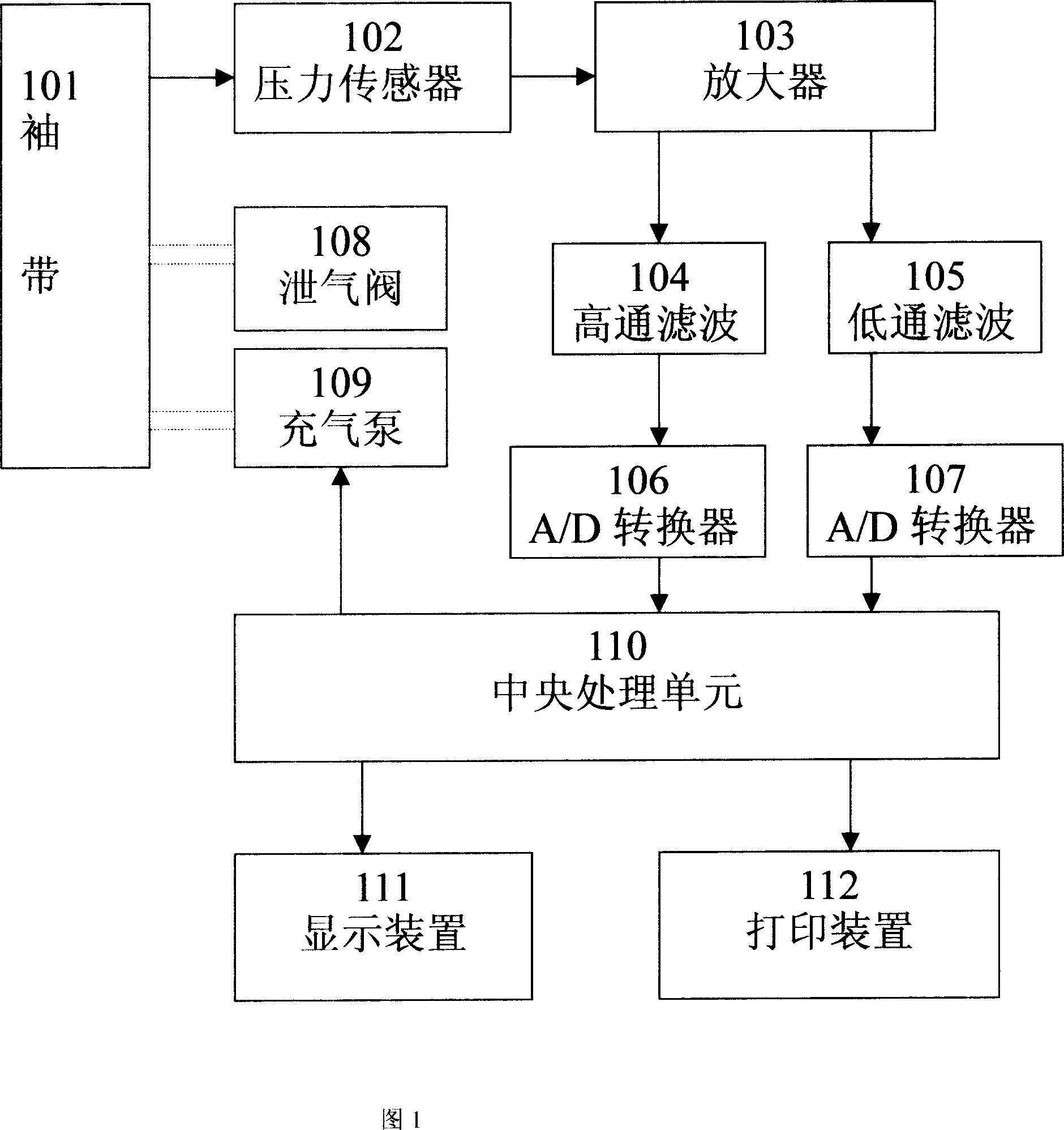
The present invention relates to one electronic sphygmomanometer, which can output in standard figure format and perform the comparison, holding and repeated judgment of measured blood pressure. The electronic sphygmomanometer includes a cuff, an inflator, a deflator, a pressure signal converter, a pulse detector, a cuff pressure detector, a figure generator, a blood pressure decider, a display and a printer. The electronic sphygmomanometer capable of outputting standardized figure can complete comparison in different blood pressure measuring method and comparison of blood pressure values measured by different users.

Description

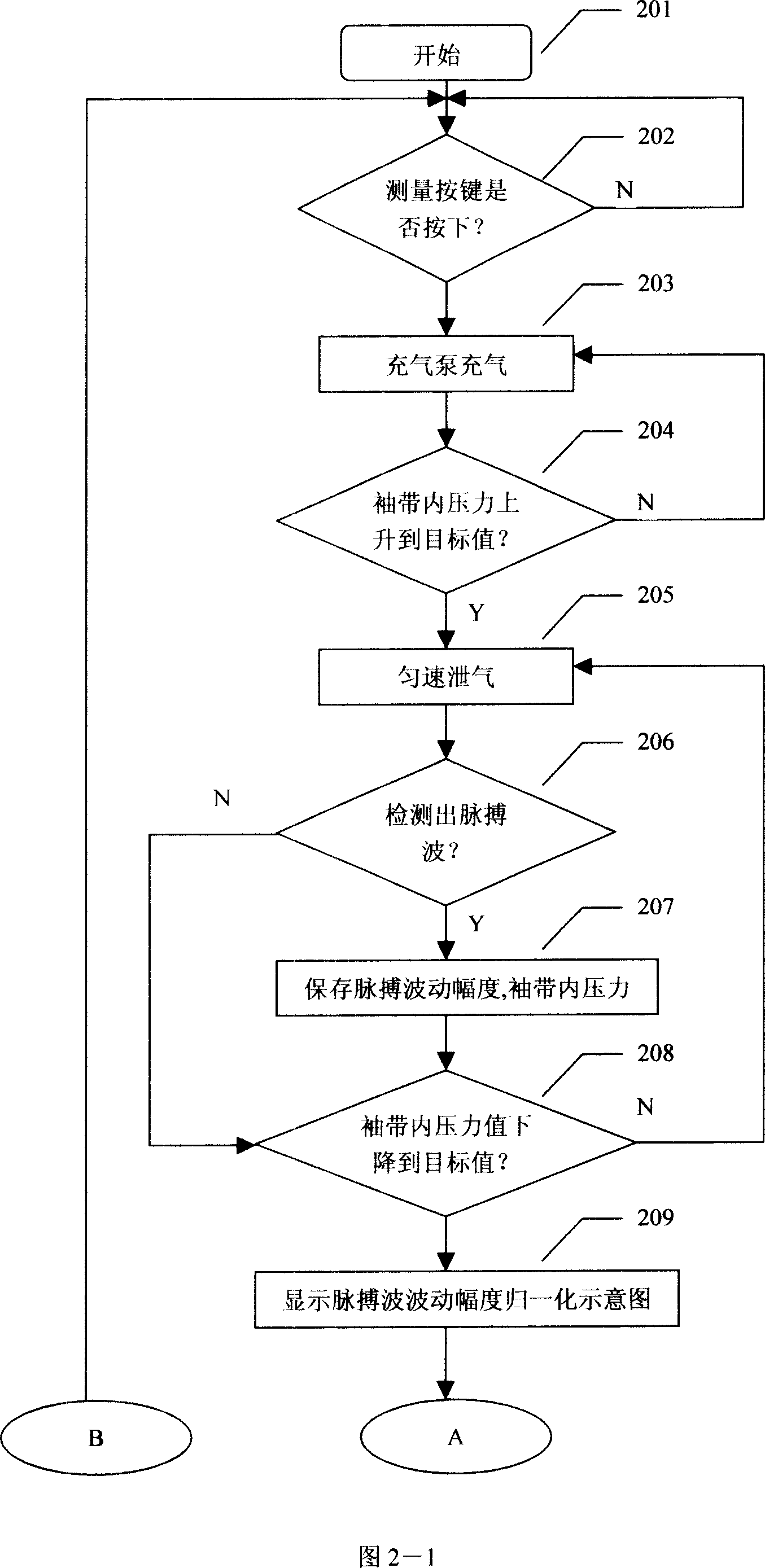
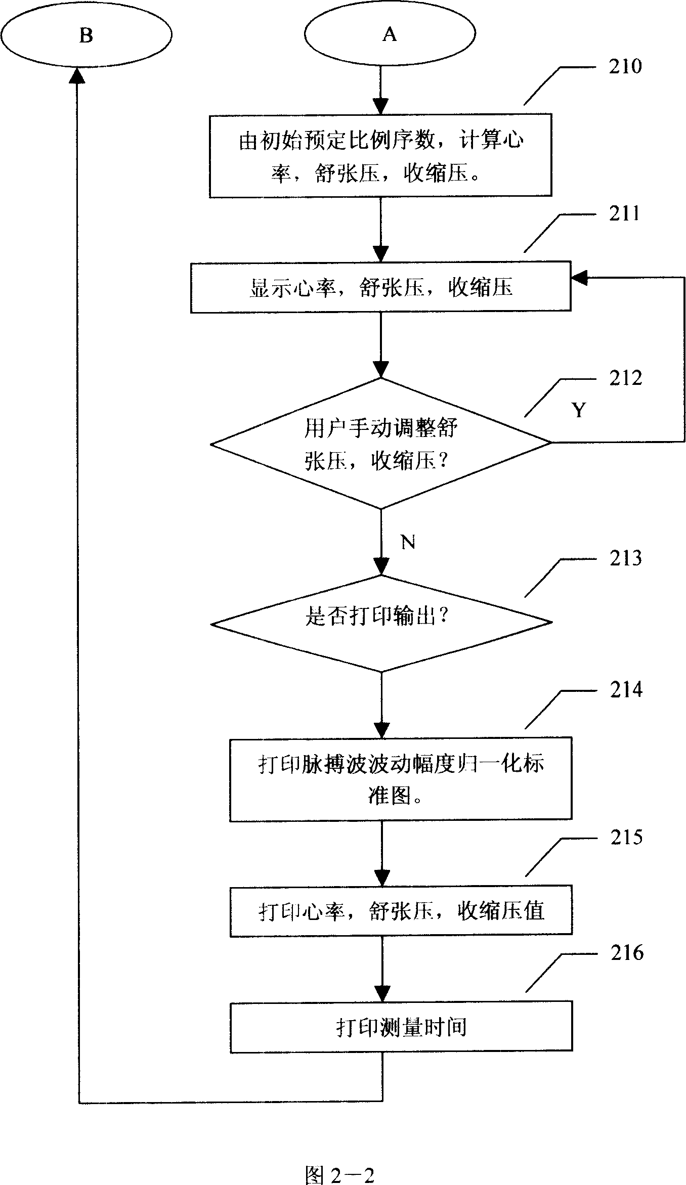
technical field [0001] The invention relates to an electronic sphygmomanometer. The electronic sphygmomanometer generates a normalized pulse wave fluctuation amplitude graph, displays and prints the graphic format, and realizes the comparison and repeated judgment of blood pressure measurement. Background technique [0002] At present, most blood pressure monitors and electronic sphygmomanometers use the oscillometric method to measure blood pressure. The oscillometric method of measuring blood pressure requires the use of an inflatable cuff or wristband to block the arterial blood flow, and then deflate slowly. During the process of deflation, the pressure oscillation wave in the cuff is detected. The pressure oscillation wave is also called pulse wave, which comes from The pulsation of the blood vessel wall. When the static pressure in the cuff or wristband is greater than the systolic pressure, the artery is closed, and small oscillation waves appear in the cuff or wrist...

Claims


Application Information

Patent Timeline
Patent Type & Authority Applications(China)
IPC IPC(8): A61B5/0225
Inventor 王超文
Owner 王超文
Learn More