
Phase locked loop having reduced inherent noise

a phase lock and inherent noise technology, applied in the field of phase lock loops, can solve the problems of poor frequency/phase detector discrimination, inherent noise of phase lock loop, etc., and achieve the effect of reducing the noise of the control loop

Inactive Publication Date: 2010-04-06
POLARIS INNOVATIONS LTD
View PDF6 Cites 0 Cited by
  • Summary
  • Abstract
  • Description
  • Claims
  • Application Information

AI Technical Summary

Benefits of technology

[0007]Aspects of the present invention provide a phase locked loop and a method for operating a phase locked loop wherein the inherent noise of the control loop can be reduced.
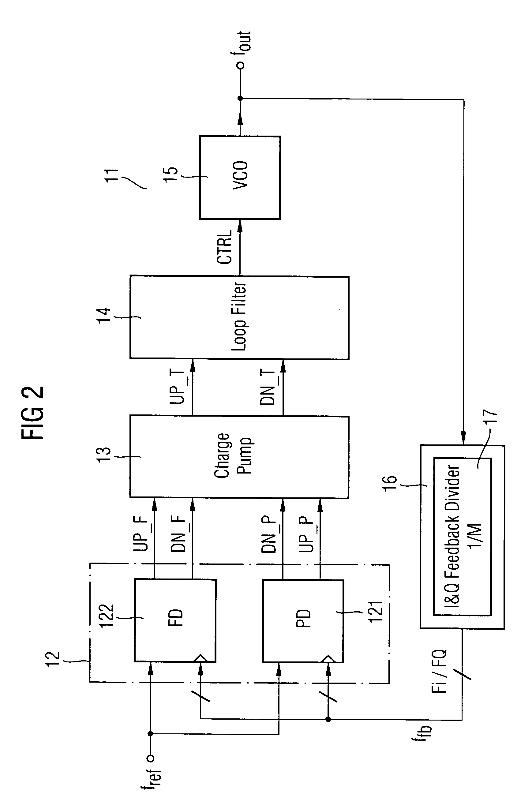
[0009]One idea of the present invention is to provide more than one feedback signal each of which are phase shifted to the frequency / phase detection. In the phase locked loop, the input signal is sampled with the feedback signal, and the provision of a plurality of feedback signals allows for an “oversampling” of the input signal whereby the discrimination accuracy is increased, i.e., the phase and / or the frequency difference between the input signal and the output signal can be determined more precisely. This allows for improving the control of the output signal frequency as the control is related to the determined and more precise phase and / or frequency differences. The improved control of the output signal frequency results in a reduced inherent noise of the output signal.

Problems solved by technology

As the discrimination of the frequency / phase detector is poor due to the mere detection of a leading and lagging of the feedback signal, a phase locked loop according to the prior art produces an inherent noise as a result of a frequency toggling around the nominal output frequency.
This also results in an inherent noise of the output frequency depending on the poor discrimination of the frequency / phase detection.

Method used


Image

  • Phase locked loop having reduced inherent noise
  • Phase locked loop having reduced inherent noise
  • Phase locked loop having reduced inherent noise

Examples


Embodiment Construction

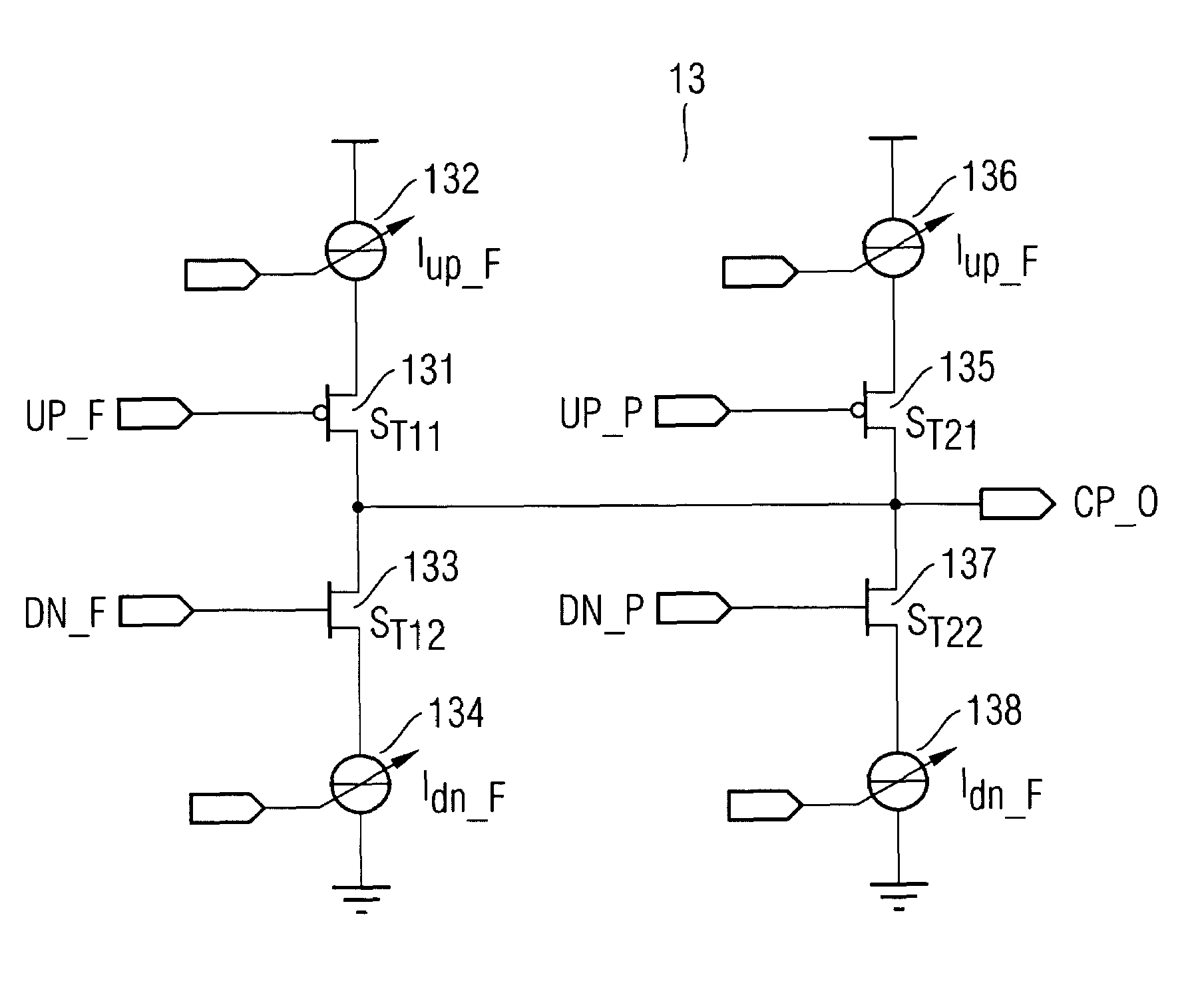
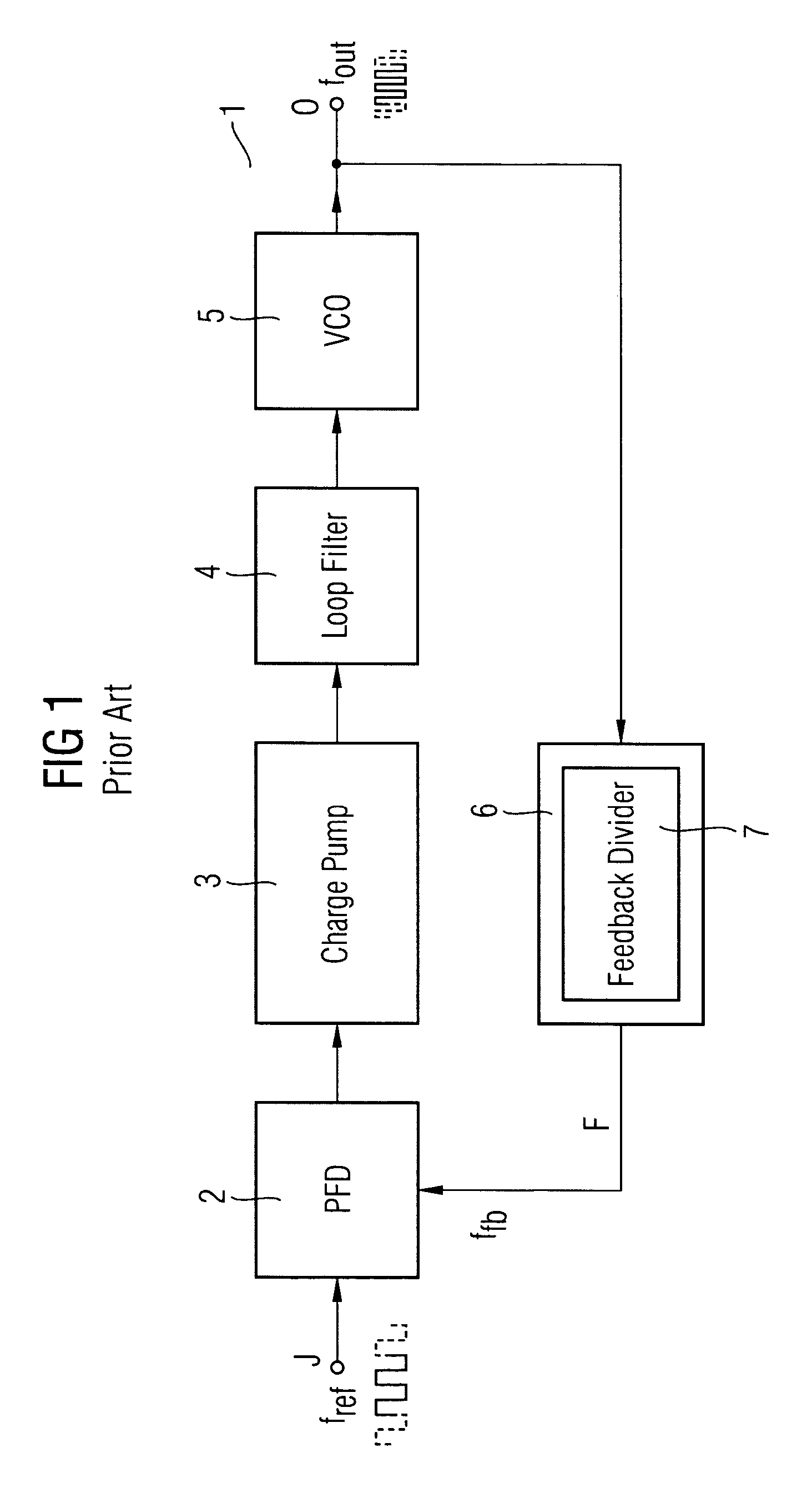
[0053]In FIG. 1, a block diagram of an analog phase locked loop circuit 1 is depicted. The phase locked loop circuit 1 comprises a phase / frequency detector (PFD) 2 which receives an input signal J having an input frequency fref and a feedback signal F having a feedback frequency ffb. The phase / frequency detector 2 compares the input signal J and the feedback signal F and supplies a leading / lagging information to a charge pump circuit 3. The charge pump 3 transforms the leading / lagging information to current pulses which are provided via a loop filter 4 to a voltage controlled oscillator (VCO) 5 which provides an output signal O having a frequency fOUT. The output of the voltage controlled oscillator 5 is coupled to a feedback loop, and the output of the feedback loop provides the feedback signal F supplied to the respective input of the phase / frequency detector 2 as mentioned above.

[0054]Such a phase locked loop circuit is known in the art and provides an output signal O having a fr...


PUM


Abstract

A phase locked loop having reduced inherent noise is provided. The phase locked loop comprises a controlled oscillator for outputting a periodic output signal as a result of a control signal; a feedback unit for providing at least two periodic feedback signals having a constant phase shift to each other and each depending on the output signal; a phase / frequency detector for providing difference signals each depending on a periodic input signal and at least one of the feedback signals; and a control circuit for providing the control signal to the controlled oscillator depending on the difference signals.

Description

BACKGROUND OF THE INVENTION[0001]1. Field of the Invention[0002]The present invention is related to phase locked loops for providing an output signal depending on a periodic input signal. The present invention is further related to phase locked loops having analog or digital phase control loops.[0003]2. Description of the Related Art[0004]An analog phase locked loop circuit usually includes a frequency / phase detector, a charge pump, a loop filter and a voltage controlled oscillator as well as a feedback unit for feeding back the output signal to the frequency / phase detector. The frequency / phase detector is usually provided to compare the input signal with a feedback signal supplied by the feedback unit such that a leading / lagging information is obtained. If the feedback signal is lagging with respect to the input signal, the leading / lagging information results in an increased voltage supplied to the voltage controlled oscillator in such a way that the output signal is increased in i...

Claims


Application Information

Patent Timeline
Patent Type & Authority Patents(United States)
IPC IPC(8): H03D3/24
CPCH03L7/087H03L7/091H03L7/18H03L7/0995H03L7/113H03L7/0994
Inventor GREGORIUS, PETERSTREIBL, MARTINRICKES, THOMAS
Owner POLARIS INNOVATIONS LTD
Learn More