
Coil System for a Magnetic Resonance Tomography System

Active Publication Date: 2013-12-12
SIEMENS HEALTHCARE GMBH
View PDF15 Cites 0 Cited by
  • Summary
  • Abstract
  • Description
  • Claims
  • Application Information

AI Technical Summary

Benefits of technology

The invention is about a new type of coil arrangement for a magnetic resonance imaging (MRI) system. The coils are designed to be completely immersed in a cryogenic cooling medium, which allows for effective cooling without the need for bulky heat pipes. This compact design is particularly useful in limited space. Additionally, the receiving chamber may have a D-shaped cross section, which improves the signal-to-noise ratio. These technical features result in improved performance and reliability of the MRI system.

Problems solved by technology

In contrast to cooled coil arrangements known from the prior art, cooling is therefore not achieved by coupling the coils thermally to a chiller with the aid of heat pipes or similar heat-conduction apparatuses but by completely immersing the coils in a cryogenic cooling medium.

Method used


Image

  • Coil System for a Magnetic Resonance Tomography System
  • Coil System for a Magnetic Resonance Tomography System
  • Coil System for a Magnetic Resonance Tomography System

Examples


Embodiment Construction

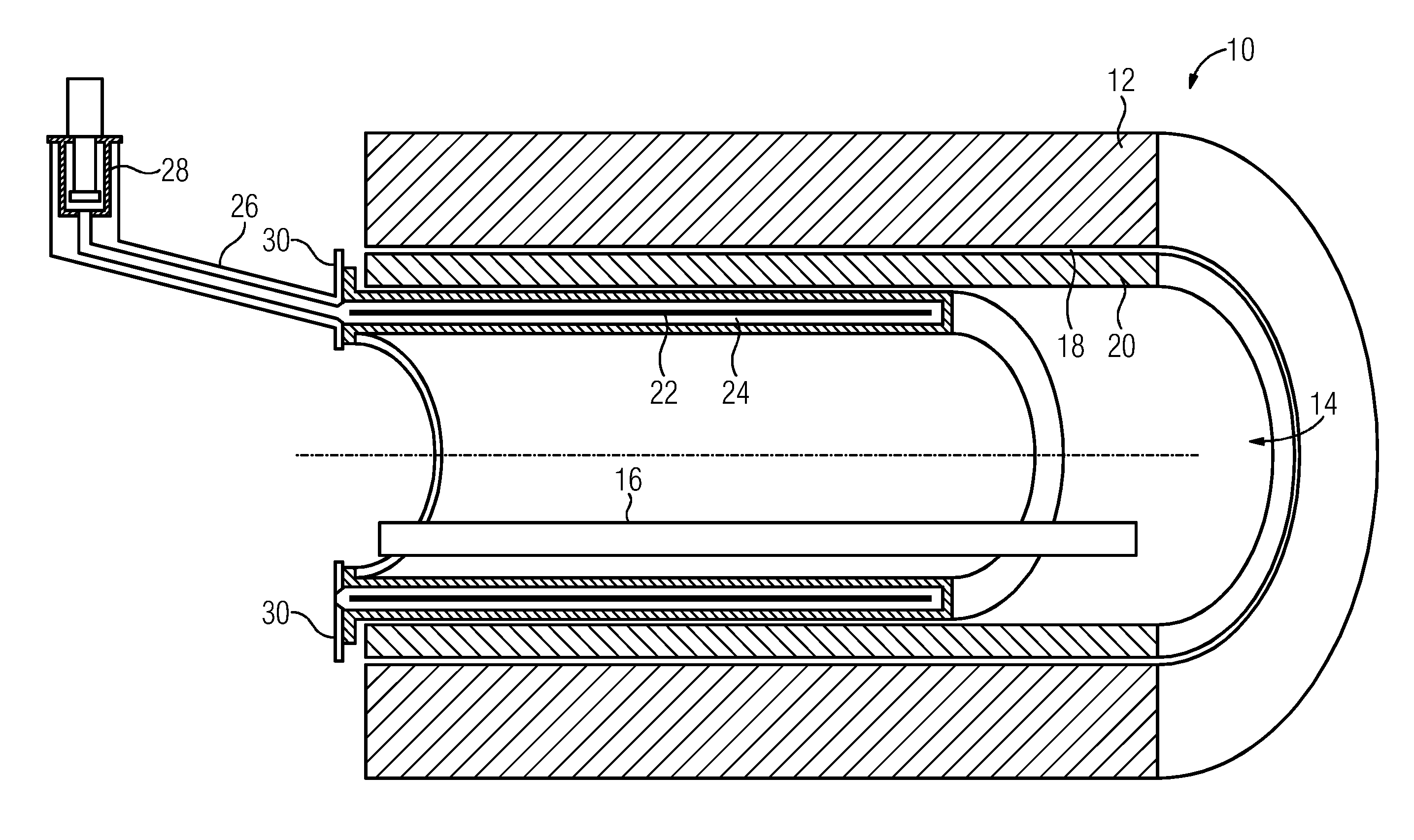
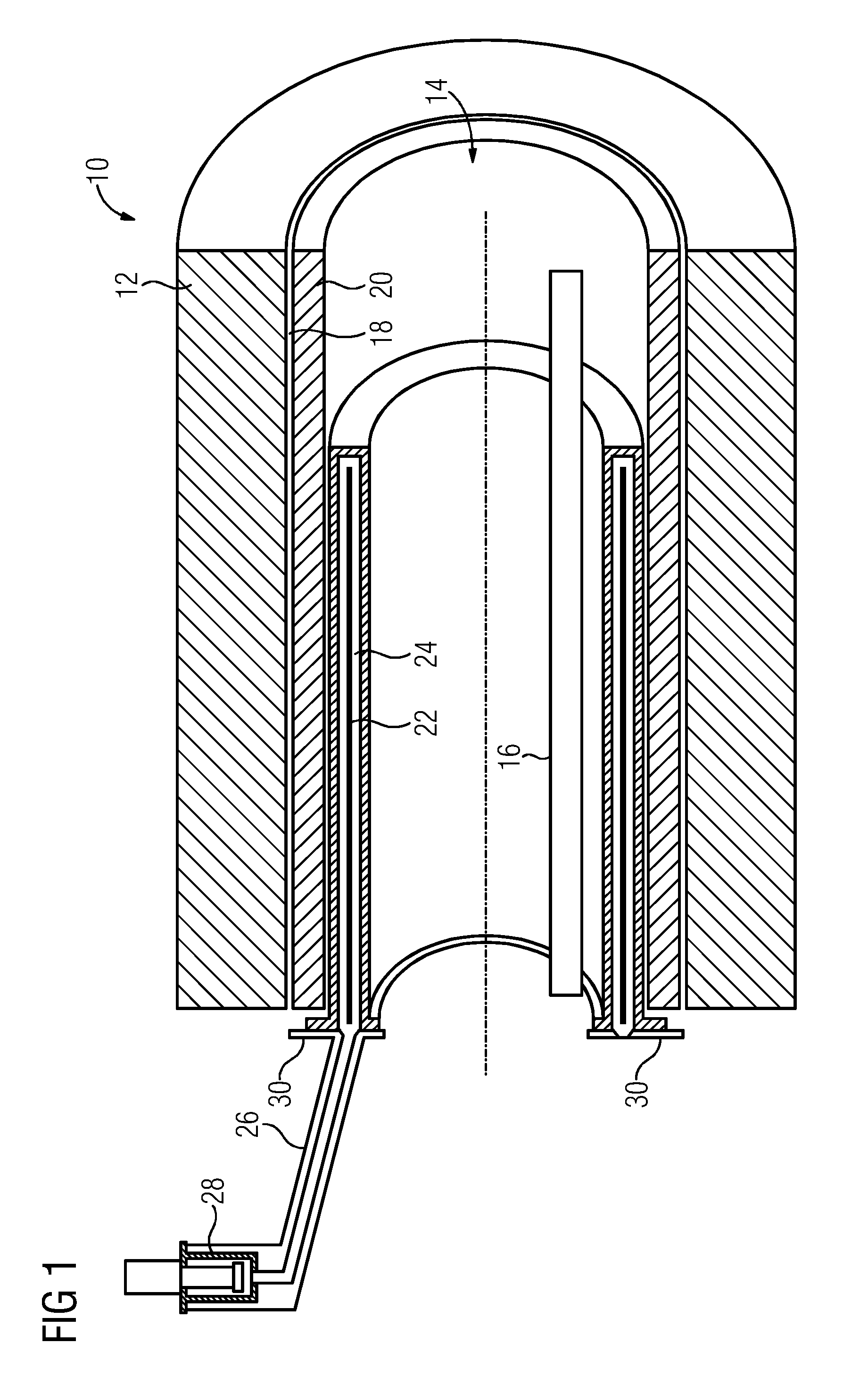
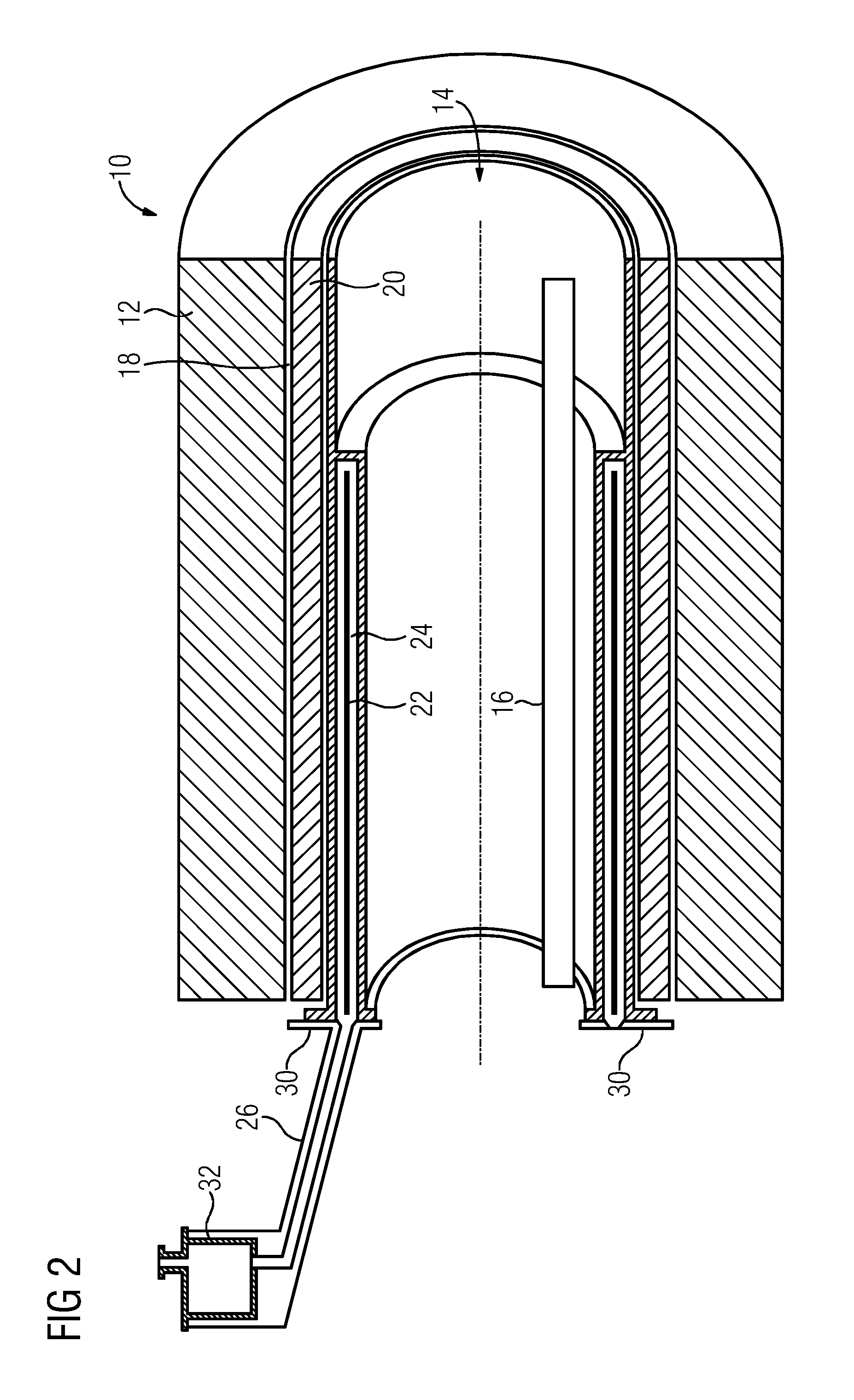
[0033]A magnetic resonance tomography system designated as a whole as 10 includes a background field magnet 12 that is configured as a hollow cylinder, in the opening 14 (e.g., bore) of which a patient couch 16 is disposed. Adjoining an inner lateral surface 18 of the background field magnet 12 is a receiving chamber 20 for gradient coils of the magnetic resonance tomography system 10.

[0034]Transmit and receive coils for high-frequency signals, which are used to excite nuclear resonance and to receive the resonance signal, are disposed in a further hollow cylindrical receiving chamber 22 that is enclosed by a vacuum jacket 24.

[0035]The receiving chamber 22 for the coils, which are not shown in detail in the figures, is connected via a coolant line 26 to a chiller 28. During operation of the magnetic resonance tomography system 10, the receiving chamber 22 is filled with a cryogenic cooling medium (e.g., liquid nitrogen, liquid helium or liquid neon), with evaporating cooling medium ...


PUM


Abstract

A coil system for a magnetic resonance tomography system includes a plurality of coils for sending and / or receiving high-frequency signals. The plurality of coils is disposed in a receiving chamber between a tomography magnet and a lining of an opening in the tomography magnet and may be cooled by a cooling apparatus. When the coil system is in an operating state, the receiving chamber is filled with a cryogenic cooling medium.

Description

[0001]This application claims the benefit of DE 10 2012 209 754.6, filed on Jun. 12, 2012, which is hereby incorporated by reference.BACKGROUND[0002]The present embodiments relate to a coil system for a magnetic resonance tomography system (e.g., a nuclear spin tomography system).[0003]Magnetic resonance tomography is a method for diagnosing a large number of diseases using imaging. A magnetic resonance tomography system may include at least a background field magnet, a gradient system and high-frequency coils for sending and receiving the high-frequency magnetic resonance signal.[0004]In whole-body magnetic resonance tomography systems, the high-frequency coils may be local field coils that are partially integrated in a patient couch, are to be positioned partially on and around the body of the patient or are disposed in the manner of a helmet around the head. Positioning and removing such local field coils takes time and effort, and the presence of the local field coils in the rel...

Claims


Application Information

Patent Timeline
IPC IPC(8): G01R33/34
CPCG01R33/34023G01R33/34015G01R33/3403G01R33/3415G01R33/34G01R33/341F17C7/00F17C7/02F17C9/00
Inventor OOMEN, MARIJN PIETERREHNER, ROBERTVAN HA ELT, PETER
Owner SIEMENS HEALTHCARE GMBH
Learn More