Light reflection device with defined outline definition light distribution

A technology of light reflectors and reflectors, which can be used in the direction of reflectors, light source fixation, lighting device components, etc., and can solve problems such as no outline

Inactive Publication Date: 2007-11-28
AUER LIGHTING
View PDF4 Cites 13 Cited by
  • Summary
  • Abstract
  • Description
  • Claims
  • Application Information

AI Technical Summary

Problems solved by technology

For example, a reflector with contour sharpness K1, corresponding to S(γ) > 4, has a clearly defined boundary without scattered light, but a reflector with contour sharpness K5, corresponding to S(γ) < 0.5, has Large radiation borders without detectable contours

Method used


Image

  • Light reflection device with defined outline definition light distribution
  • Light reflection device with defined outline definition light distribution
  • Light reflection device with defined outline definition light distribution

Examples


Embodiment Construction

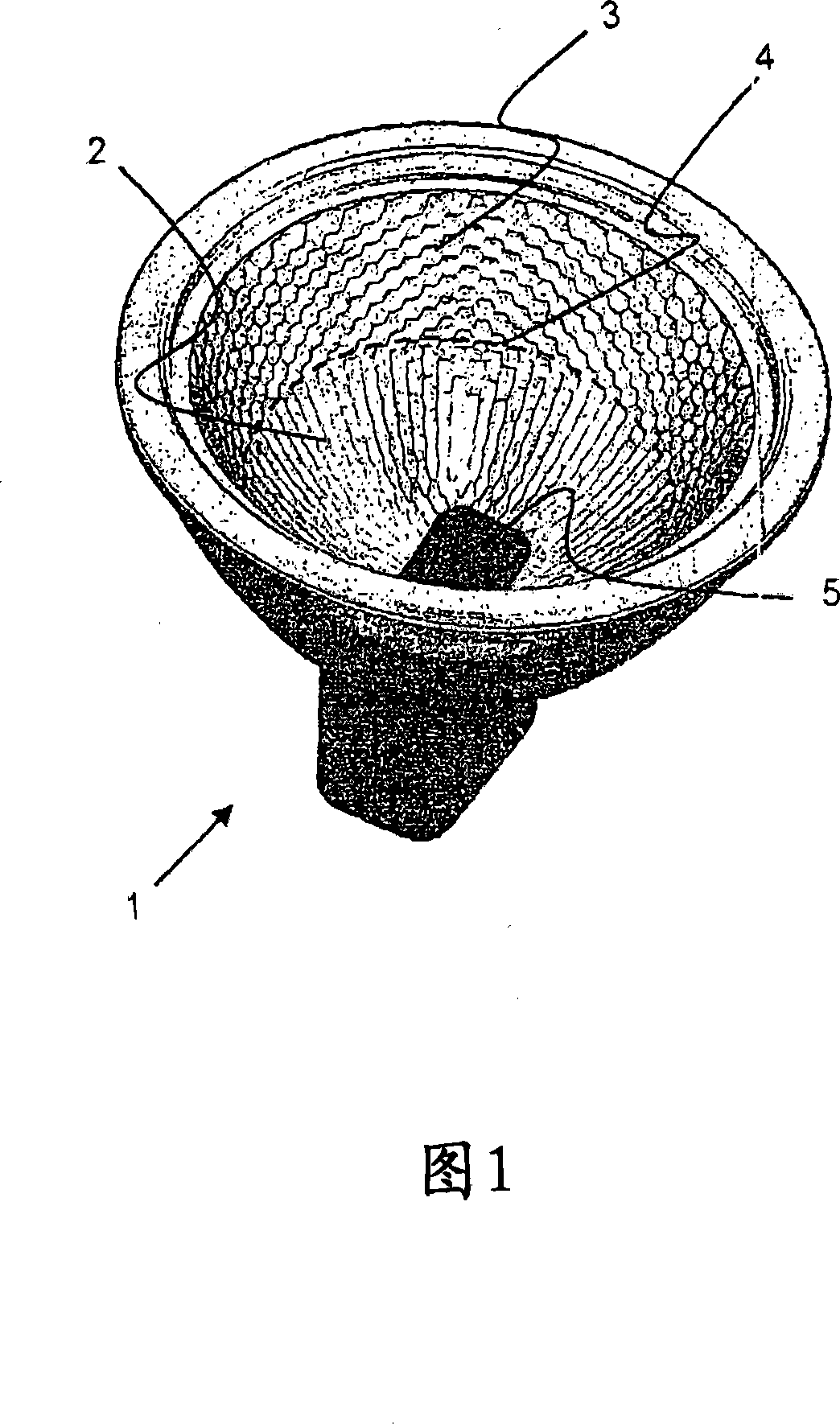
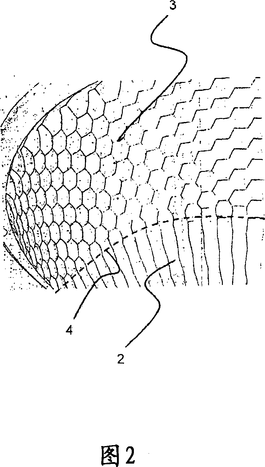
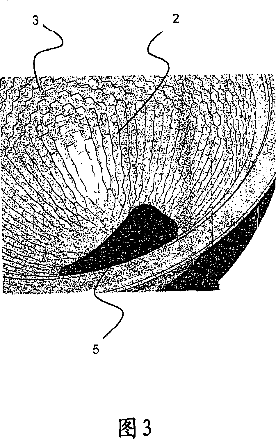
[0054] Next, a preferred embodiment of the reflector and its lighting unit according to the present invention will be described with reference to the accompanying drawings.

[0055] In this description, a cylindrical facet is understood to be that part of a cylinder whose longitudinal axis approximately corresponds to the tangent to the basic shape of the reflector close to the facet, in particular closest to the facet, against which the reflector .

[0056] The basic shape of the reflector is understood to mean that in the case of facet-free reflectors it can preferably have a spherical, elliptical or parabolic basic shape.

[0057] Furthermore, the cross-sectional axis of the cylinder defining the shape of the facets lies in the plane of the optical axis of the reflector, unless otherwise specified in the description of the specific embodiment. As a result, such cylindrical facets have the appearance of radial spoke-shaped sections when the reflector is viewed from the fron...


PUM


Abstract

The invention relates to a light reflector comprising a reflective surface having facets at least in sections, and a region for arranging at least one luminous means, wherein facets in a first region, closer to the region for arranging at least one luminous means, the region close to the luminous means, have a cylindrical shape, and facets in a second region, more remote from the region for arranging at least one luminous means, the region remote from the luminous means, have a spherical shape.

Description

technical field [0001] The invention relates to a light reflector, in particular to a light reflector for a light source and a lighting unit. Background technique [0002] Light reflectors having a substantially cylindrical or rotationally symmetrical concave body are known for lighting purposes, such as spherical or parabolic reflectors. [0003] Reflectors with faceted reflective surfaces are known. Thus, for example, US 6,206,549 shows a light reflector having an at least segmented surface. [0004] EP 87 305 285 describes a reflector whose reflective surface is at least partially covered with facets having an elliptical circumference which respectively adjoin the elliptical circumferences of adjacent facets and expose an original area between these, That is to say non-faceted reflector surfaces, which overall lead to lower scattering losses for these reflectors than in the case of reflectors whose facets directly adjoin each other in a hexagonal or rhomboid shape. [...

Claims


Application Information

Patent Timeline
Patent Type & Authority Applications(China)
IPC IPC(8): F21V7/10F21V7/04F21V7/09G02B5/08
CPCF21V7/09F21V19/0005
Inventor H·瓦格纳R·基特尔曼
Owner AUER LIGHTING
Why Eureka
Try Eureka