Door drive mechanism, especially revolving door drive mechanism

A drive device and door drive technology, applied in door/window fittings, power control mechanisms, switches with brakes, etc., can solve the problem that the door torque distribution cannot be optimized, increase the effective piston area, and reduce the working pressure. , The effect of avoiding the load of mechanical structural components

Inactive Publication Date: 2007-11-28
DORMA GMBH & CO KG
View PDF3 Cites 5 Cited by
  • Summary
  • Abstract
  • Description
  • Claims
  • Application Information

AI Technical Summary

Problems solved by technology

Although this revolving door drive can be installed discreetly, the door moment dist

Method used


Image

  • Door drive mechanism, especially revolving door drive mechanism
  • Door drive mechanism, especially revolving door drive mechanism

Examples


Embodiment Construction

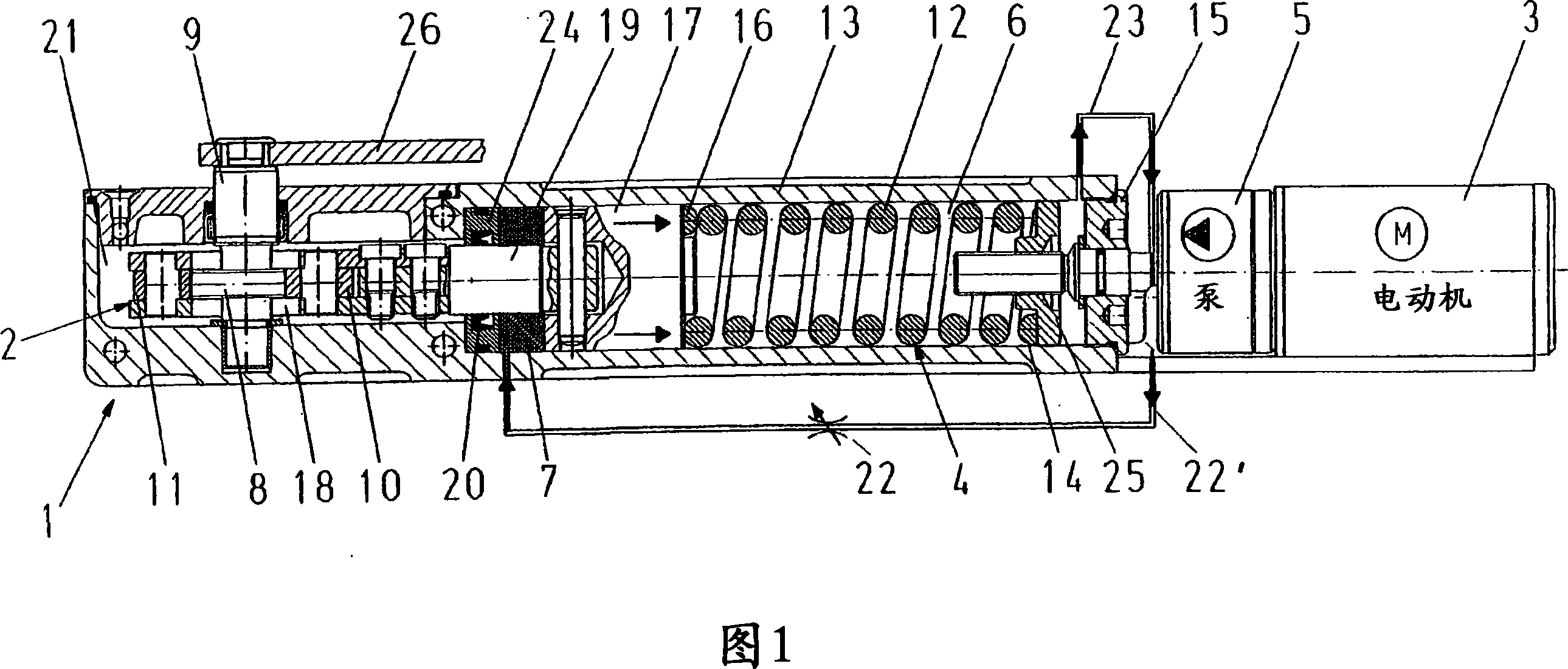
[0018] FIG. 1 shows a door operator 1 according to the invention, which can be designed in particular as a revolving door operator. The door operator 1 has a drive unit 2 which can be connected via an output shaft 9 to a door (not shown in FIG. 1 ), for example via a lever 26 and a slide rail with a sliding block. The drive unit 2 is arranged in a housing 13 .

[0019] Furthermore, the door operator 1 has an electric motor 3 and a spring accumulator 4 arranged in the housing 13 , which is connected to the electric motor 3 and the drive unit 2 .

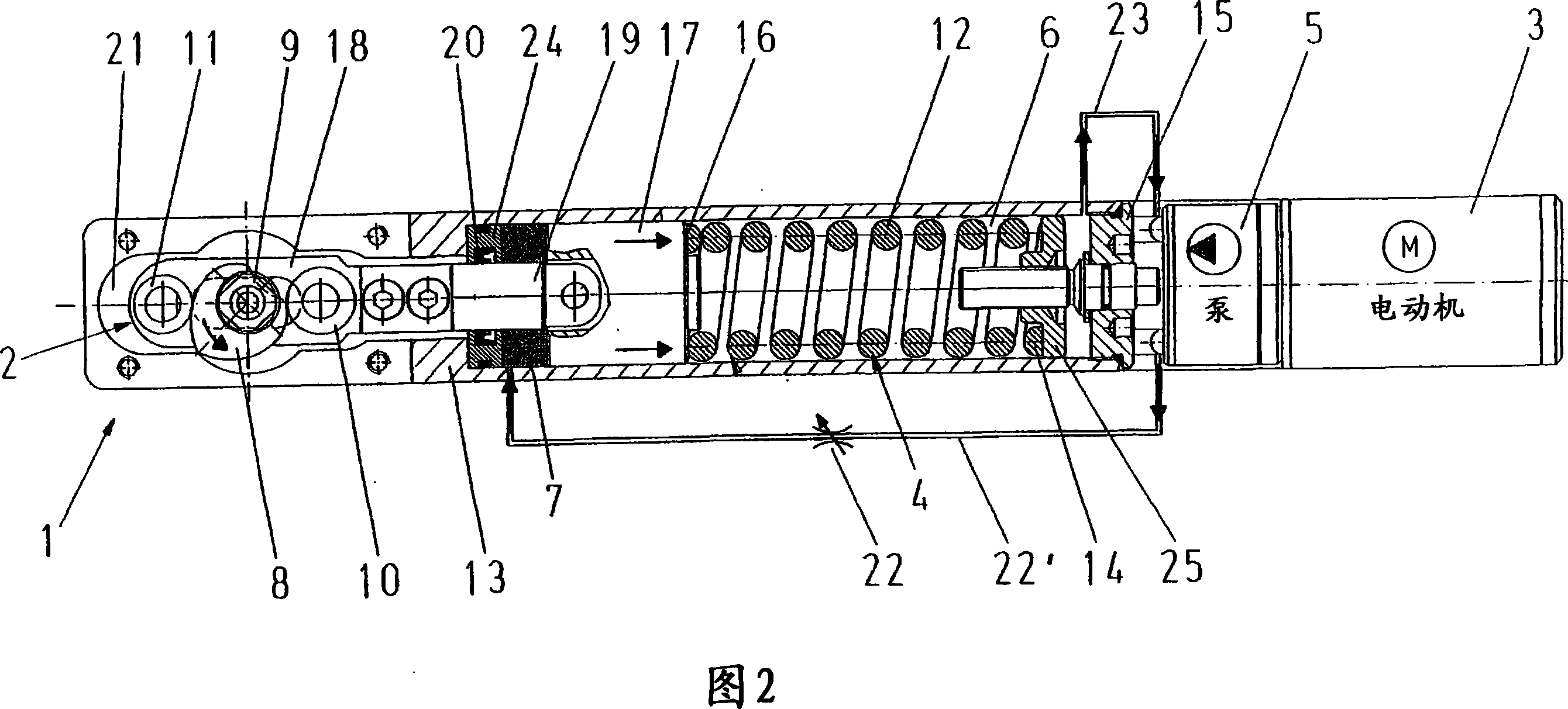
[0020] As shown in FIGS. 1 and 2 , the electric motor 3 is drivingly connected to a hydraulic pump 5 . In the described embodiment, the electric motor 3 and the hydraulic pump 5 are installed on the casing 13 , but they can also be flanged separately or combined on the casing 13 . The electric motor 3 is hydraulically connected via a hydraulic pump 5 and a first hydraulic line 22 ′ to a pressure chamber 7 which is associated with th...


PUM


Abstract

A door operator includes a housing; a hydraulic compartment providing a reservoir volume; a sealed pressure compartment; a drive unit disposed in the housing and coupleable to a door via an output shaft; a hydraulic pump in hydraulic connection with the hydraulic compartment and the sealed pressure compartment; a motor in driving relationship with the hydraulic pump; and a spring force accumulator disposed in the housing. The spring force accumulator is associated with the sealed pressure compartment and coupled to the drive unit.

Description

technical field [0001] The invention relates to a door operator, in particular a revolving door operator, according to the preamble of claim 1 . Background technique [0002] Such a door operator is known from DE 295 21 068 U1. From DE 40 38 720 C2 a top door closer with a sliding rail linkage is known, which has a cam drive unit which provides an optimum door torque distribution and operating comfort. So in principle this top door closer is also suitable as a door drive, but experiments done within the scope of the invention have shown that when oil pressure is applied to the drive unit, a very unfavorable conversion of the hydraulic pressure produces reciprocation / rotation Movement and new reciprocating motion. Since the spring force accumulator for tensioning such a door closer requires about 75% of the power to be applied, only about 25% of the power needs to be delivered by the system for door acceleration. Furthermore, it is also desirable to keep such door closers ...

Claims


Application Information

Patent Timeline
IPC IPC(8): E05F3/22E05F3/10
CPCE05F15/127E05F15/04E05Y2800/113E05F3/104E05F3/224E05Y2900/132E05F3/223E05F15/53E05F15/63
Inventor V·比内克
Owner DORMA GMBH & CO KG
Why Eureka
Try Eureka