Lift facility with a braking device and method for braking a lift facility

一种制动设备、电梯的技术,应用在机械设备、制动器类型、松弛调节器等方向,能够解决制动设备进入制动动作的时间增加等问题,达到舒适引导的效果

Inactive Publication Date: 2007-12-05
INVENTIO AG
View PDF2 Cites 9 Cited by
  • Summary
  • Abstract
  • Description
  • Claims
  • Application Information

AI Technical Summary

Problems solved by technology

This also has the effect that the time for the brake system to come into braking action is correspondingly increased, or suitable wear-resistant brake pads must be used

Method used


Image

  • Lift facility with a braking device and method for braking a lift facility
  • Lift facility with a braking device and method for braking a lift facility
  • Lift facility with a braking device and method for braking a lift facility

Examples


Embodiment Construction

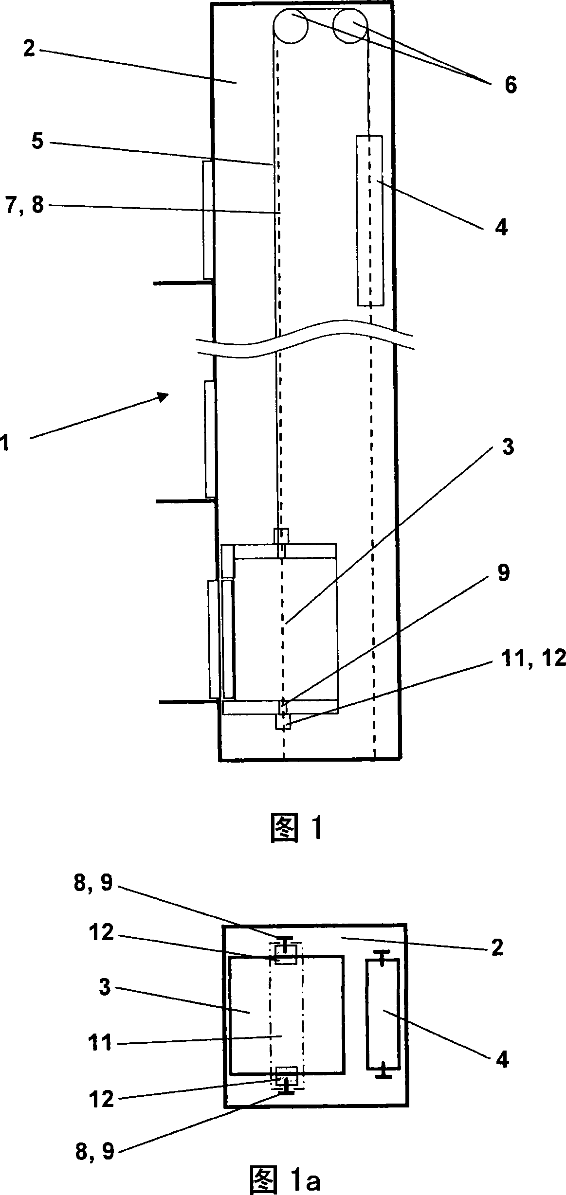
[0039] A possible overall configuration of the elevator installation is shown in Figures 1 and 1a. Figure 1 shows an elevator installation 1 in a schematic side view, and Figure 1a shows the same elevator installation 1 in a schematic plan view. The illustrated elevator installation 1 comprises an elevator car 3 moving in a vertical direction in a shaft 2 along guide rails 7. The elevator car 3 is supported by the supporting device 5 and connected to the counterweight 4. The counterweight 4 and the elevator car 3 are driven by the driver 6 through the supporting device 5 and move toward each other in the elevator shaft 2. The elevator car 3 is provided with a braking device 11 that brakes the elevator car or keeps the elevator car stationary. The braking device 11 includes at least two braking units 12, each braking unit 12 acting on a corresponding guide rail 7. The braking unit 12 cooperates as a single braking device 11, wherein the braking device 11 can selectively define the ...


PUM


Abstract

To provide an elevator device having an elevator cage vertically moving along a guide track.If necessary, the elevator cage is braked by a brake or kept stationary. The brake comprises at least two brake units 12. A wear compensation device 30 is mounted on at least one or desirably each of the brake units 12. When the brake units 12 are released, they set a clearance lf, namely the free interval thereof from the brake surface related to a brake lining 15. The free interval corresponds to a specified value when a brake part is released. Consequently, a normal and economical brake material which may wear during braking can be used.

Description

Technical field [0001] The invention relates to an elevator installation with a car and a method of braking the car. Background technique [0002] The elevator equipment is installed in the shaft. Shafts are usually made of solid building materials, but shafts can also be at least partially open. The elevator installation generally includes a car for transporting people and / or goods. The car is connected to the counterweight through a supporting device. The car moves along a substantially vertical car travel path by selectively acting on the support device or directly on the car or counterweight, and is maintained at the stopping point or braked from the running state to a stop by the brake status. [0003] The function of the brake arranged at the driver is usually to hold and brake in an operating state, and the role of the safety brake device arranged at the car is to hold and brake in an emergency state. For example, the operating status includes the normal operating sequence...

Claims


Application Information

Patent Timeline
Patent Type & Authority Applications(China)
IPC IPC(8): B66B5/16
CPCF16D65/54B66B5/16F16D63/008
Inventor 尼古拉斯·格里蒙德汉斯·柯什乔瑟夫·A·莫夫
Owner INVENTIO AG
Why Eureka
Try Eureka