Check patentability & draft patents in minutes with Patsnap Eureka AI!

Back light module unit and LCD device

A technology of backlight module and liquid crystal panel, applied in optics, nonlinear optics, instruments, etc., can solve the problem of high production cost of reflector grounding, and achieve cost-saving effect

Inactive Publication Date: 2007-12-05
INNOCOM TECH SHENZHEN +1
View PDF0 Cites 0 Cited by
  • Summary
  • Abstract
  • Description
  • Claims
  • Application Information

AI Technical Summary

Problems solved by technology

[0005] In order to solve the problem of high production cost of reflector grounding in the prior art, the present invention provides a cost-saving backlight module

Method used


Image

  • Back light module unit and LCD device
  • Back light module unit and LCD device
  • Back light module unit and LCD device

Examples


Embodiment Construction

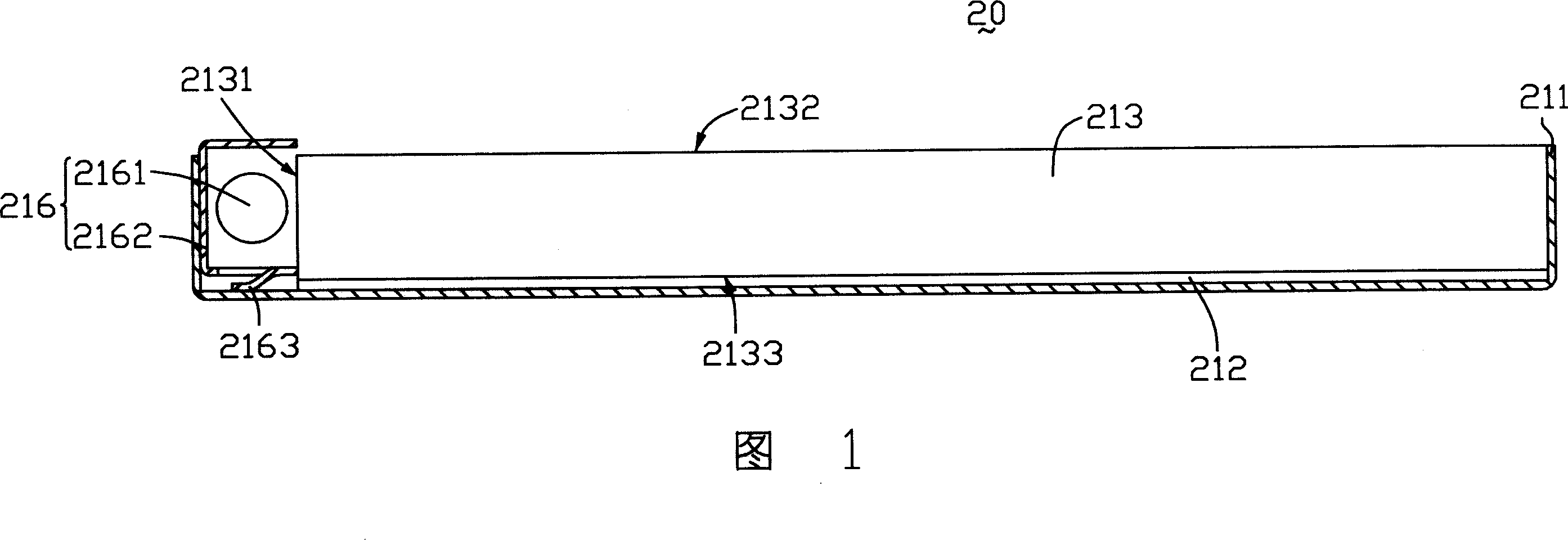
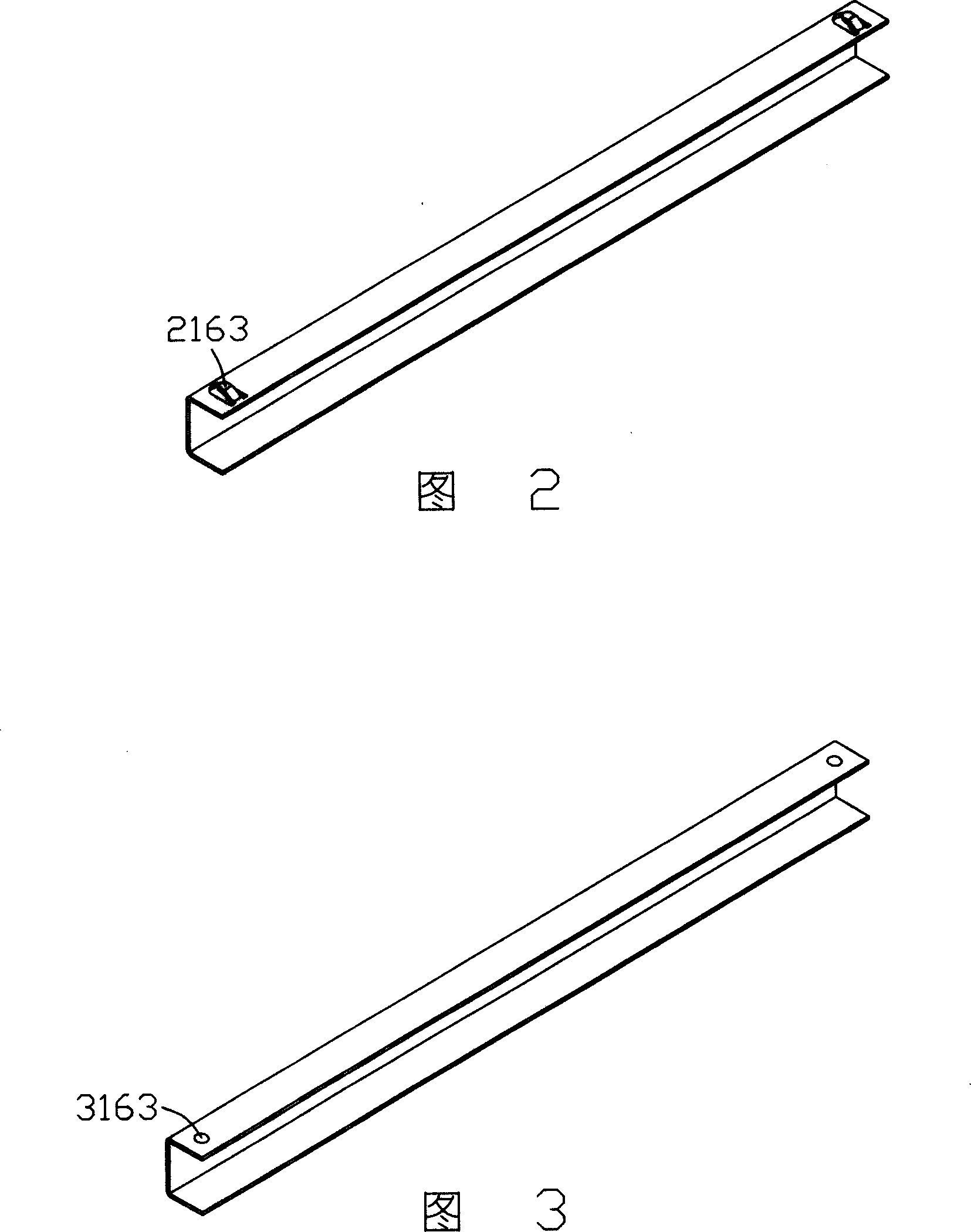
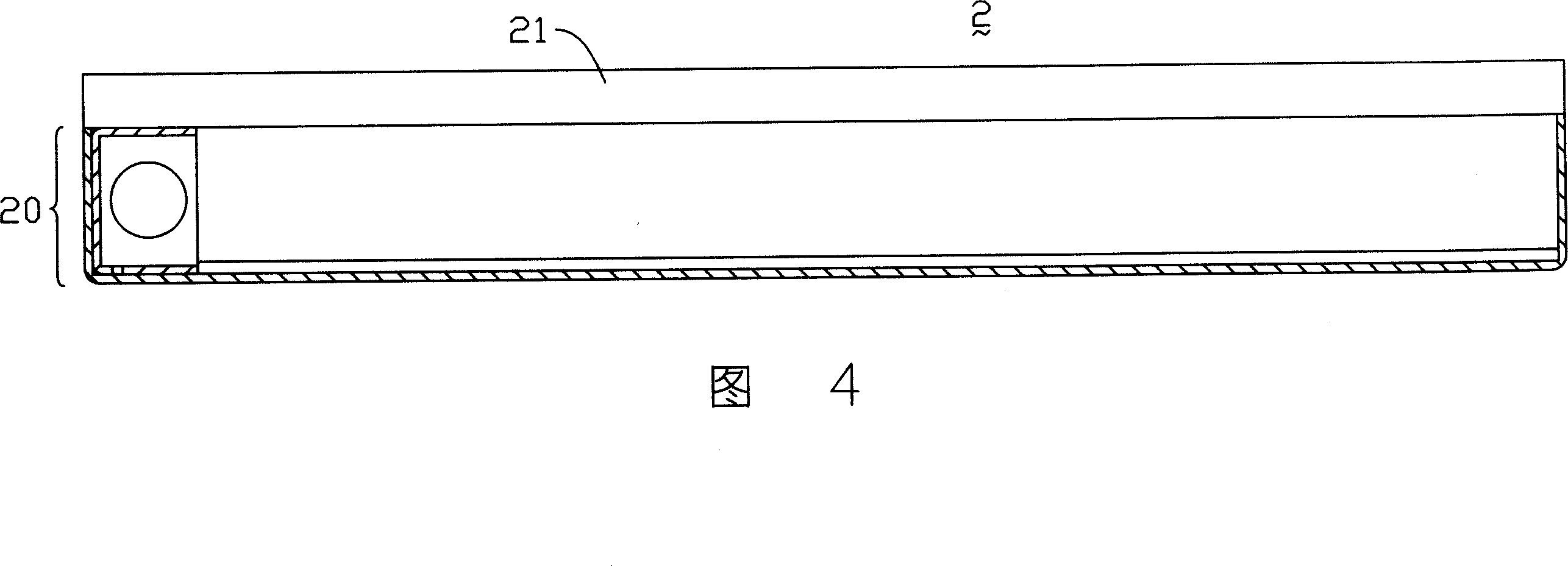
[0014] The backlight module 20 of the present invention is shown in Figure 1, and the backlight module 20 includes a back frame (bottom bezel) 211, a reflector 212, a light guide plate 213 and a lamp group 216, and the lamp group 216 includes a The lamp tube 2161 and a lamp reflector 2162 are integrally formed with elastic pieces 2163 on the bottom surface of the reflector 2162 .

[0015] The light guide plate 213 includes a light incident surface 2131 , a light exit surface 2132 intersecting the light incident surface 2131 , and a bottom surface 2133 opposite to the light exit surface 2132 .

[0016] The lamp tube 2161 is in the shape of a strip, and it is arranged opposite to the light incident surface 2131. The reflector 2162 accommodates the lamp tube 2161. The reflector 212 is arranged on the bottom surface 2133 of the light guide plate 213. The back frame 211 accommodates the plate 212 , light guide plate 213 and lamp tube group 216 . The reflector 2162 is electrically ...


PUM


Abstract

The invention discloses an aphototropism mould, which comprises the following parts: light conductive board, tube group corresponding to at least one incidence face of light conductive board, back frame to contain the light conductive board and tube group, at least one integrated connecting element with one of reflective lid or back frame, wherein the tube group has at least one reflective lid; the reflective lid connects the back frame through connecting element electrically. The invention also provides a LCD device of the aphototropism mould.

Description

technical field [0001] The invention relates to a backlight module and a liquid crystal display device using the backlight module. Background technique [0002] Liquid crystal display devices are widely used due to their characteristics of low radiation, lightness, thinness, and low power consumption. With the maturity and innovation of related technologies, there are more and more types of liquid crystal display devices. [0003] Since the liquid crystal display device is a non-self-illuminating display device, it needs to provide a side light source device, such as a backlight module, to realize the display function. A general backlight module includes a light tube and a light guide plate, and the light emitted by the light tube enters the light guide plate and is transformed into a surface light source. In order to prevent the light emitted by the lamp tube from being lost and to concentrate the light into the light guide plate as much as possible, it is necessary to arr...

Claims


Application Information

Patent Timeline
Patent Type & Authority Applications(China)
IPC IPC(8): G02F1/13357G02F1/1333G02F1/1335
Inventor 林宜甫萧志仲
Owner INNOCOM TECH SHENZHEN
Features
  • R&D
  • Intellectual Property
  • Life Sciences
  • Materials
  • Tech Scout
  • Unparalleled Data Quality
  • Higher Quality Content
  • 60% Fewer Hallucinations
Learn More