
Tree structure based routing method

A tree structure and routing technology, applied in digital transmission systems, electrical components, transmission systems, etc., can solve the problems of bandwidth consumption, high routing overhead, and increased routing method overhead, and achieve the effect of reducing routing overhead and overhead.

Inactive Publication Date: 2007-12-05
BEIHANG UNIV
View PDF0 Cites 38 Cited by
  • Summary
  • Abstract
  • Description
  • Claims
  • Application Information

AI Technical Summary

Problems solved by technology

[0004] (1) Since the above three wireless communication networks do not have a regular and pre-knowable network topology, when using these routing methods to forward data packets, in order to find a suitable path, the source node often uses flooding , this way of finding the path has great blindness, consumes a lot of bandwidth, and increases routing overhead;
[0005] (2) According to the different logical structures of the network, the existing routing methods adopt a flat structure or a layered structure. In the flat structure, each node has the same status in the routing function, and its scalability is poor, which limits the network to a certain extent. Scale; the layered structure method is complex to implement, and the routing overhead is high;
[0006] (3) In existing routing methods, it is usually necessary to establish and maintain global routing information in nodes, which will greatly increase the routing control overhead, increase the complexity of routing, and reduce the effective throughput of the network;
[0007] (4) Most of the existing routing methods adopt the proactive routing method or the on-demand routing method. Although the proactive routing method has the characteristics of small path finding delay, it will cause a waste of bandwidth resources, and it requires a lot of control. message, which increases the overhead of the routing method; although the on-demand routing method can reduce the routing overhead and improve the network throughput, there is uncertainty about whether the destination node is reachable, and it will introduce a large time delay

Method used


Image

  • Tree structure based routing method
  • Tree structure based routing method
  • Tree structure based routing method

Examples


Embodiment Construction

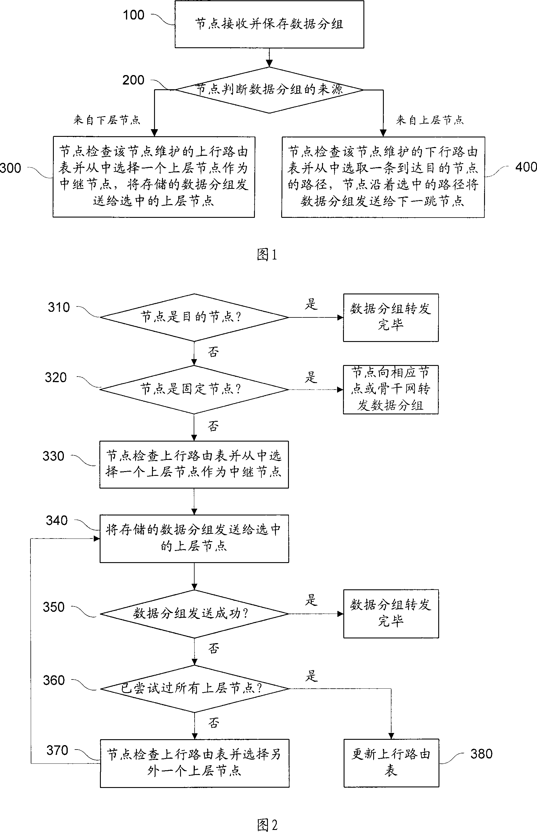
[0055] Fig. 1 is a flow chart of the routing method based on the tree structure in the present invention. Specifically:

[0056] Step 100, the node receives and saves the data packet;

[0057] Step 200, the node judges the source of the data packet, executes step 300 for the data packet from the lower node, and executes step 400 for the data packet from the upper node;

[0058] Step 300, the node checks the uplink routing table maintained by the node and selects an upper layer node as a relay node, and sends the stored data packets to the selected upper layer node;

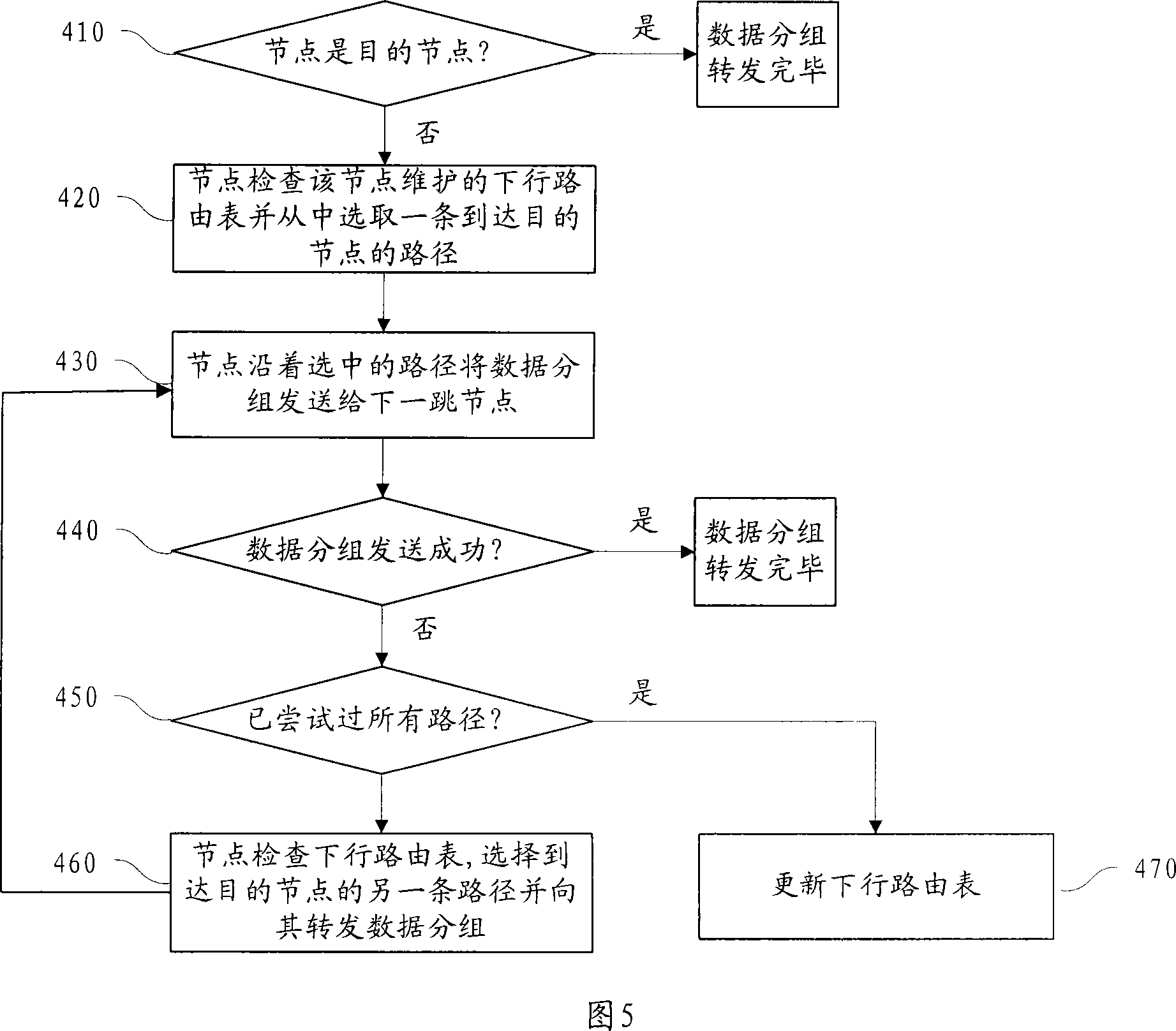
[0059] Step 400, the node checks the downlink routing table maintained by the node and selects a path to the destination node, and the node sends the data packet to the next-hop node along the selected path.

[0060] Aiming at the tree topology applicable to the wireless network, the above technical solution of the present invention proposes a stable and efficient routing method. When a node receives a data pac...


PUM


Abstract

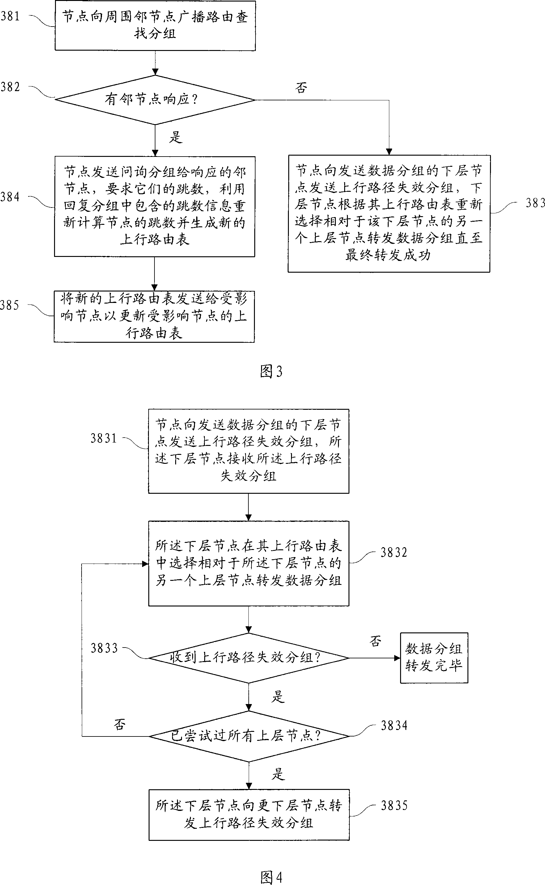
The invention relates to route method based on tree structure. It includes the following steps: judging data source after grouping; for the lower level node checking up run routing list, selecting one node as relay node, and transmitting the data grouping into the upper level node; for the upper level node checking the down run routing list, selecting one route reached to destination node, and transmitting the data grouping to the next jump node. The up run routing list records the node ID, jump number and the neighbor node ID and jump number. The down one records upper layer node list, peer node list, down run chain route information. The invention has the advantages of little control spending, high data transmitting efficiency, low bandwidth consumption, suiting for network topology dynamic change.

Description

technical field [0001] The invention relates to a routing method of a wireless network, in particular to a stable and efficient routing method based on a tree structure. Background technique [0002] With the continuous development of wireless communication technology, a variety of wireless communication network technologies have been proposed and implemented in practical applications, such as Mobile Ad Hoc Network (Mobile Ad-Hoc Network, MANET for short), Wireless Local Area Network (Wireless Local Area Network, short for WLAN) and Wireless Mesh Network (WMN for short). [0003] MANET is a distributed wireless multi-hop network composed of many mobile nodes with routing functions. It does not depend on the preset infrastructure and is temporarily formed. In the network, mobile nodes use their own wireless transceiver devices to exchange information. When within the communication range, other intermediate nodes can be used to relay to realize multi-hop communication. A WLA...

Claims


Application Information

Patent Timeline
Patent Type & Authority Applications(China)
IPC IPC(8): H04L12/56H04L12/753
Inventor 刘凯张军施璇李献昌
Owner BEIHANG UNIV
Learn More