
Display device for visually reconstructing an image

A display device, a technology for reconstructing images, applied in optics, instruments, electrical components, etc., and can solve problems such as poor image quality of reconstructed images

Inactive Publication Date: 2007-12-05
KONINKLIJKE PHILIPS ELECTRONICS NV
View PDF2 Cites 4 Cited by
  • Summary
  • Abstract
  • Description
  • Claims
  • Application Information

AI Technical Summary

Problems solved by technology

[0007] However, the image quality of the reconstructed image can be rather poor, especially at oblique viewing angles

Method used


Image

  • Display device for visually reconstructing an image
  • Display device for visually reconstructing an image

Examples


Embodiment Construction

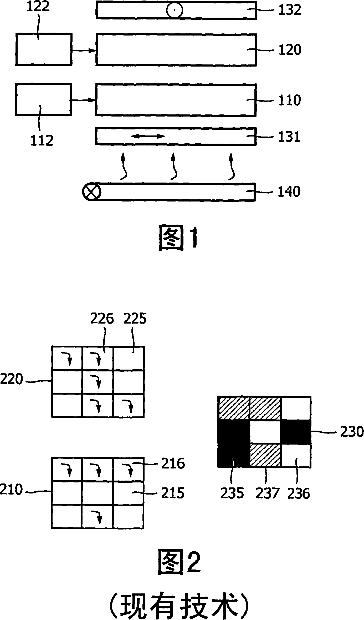
[0029] In Fig. 1, a general implementation of a transmissive display device for visually reconstructing an image from an encoded image is shown. The device includes a first liquid crystal layer 110 and a second liquid crystal layer 120 . The layers 110, 120 are arranged between crossed linear polarizers 131, 132, i.e. on one side of the LCD stack a first linear polarizer 131 with a first polarization direction is provided and on the other side of the LC stack , a second linear polarizer 132 having a second polarization direction perpendicular to the first polarization direction is provided.

[0030] The LC layer is preferably configured as a conventional white twisted nematic (TN) LC layer with a twist angle of 90 degrees. For this panel, when the pixel is powered off, the polarization direction of the passing linearly polarized light is rotated by more than 90 degrees, and when the pixel is fully powered on (maximum pixel voltage is applied), the passing linearly polarized l...


PUM


Abstract

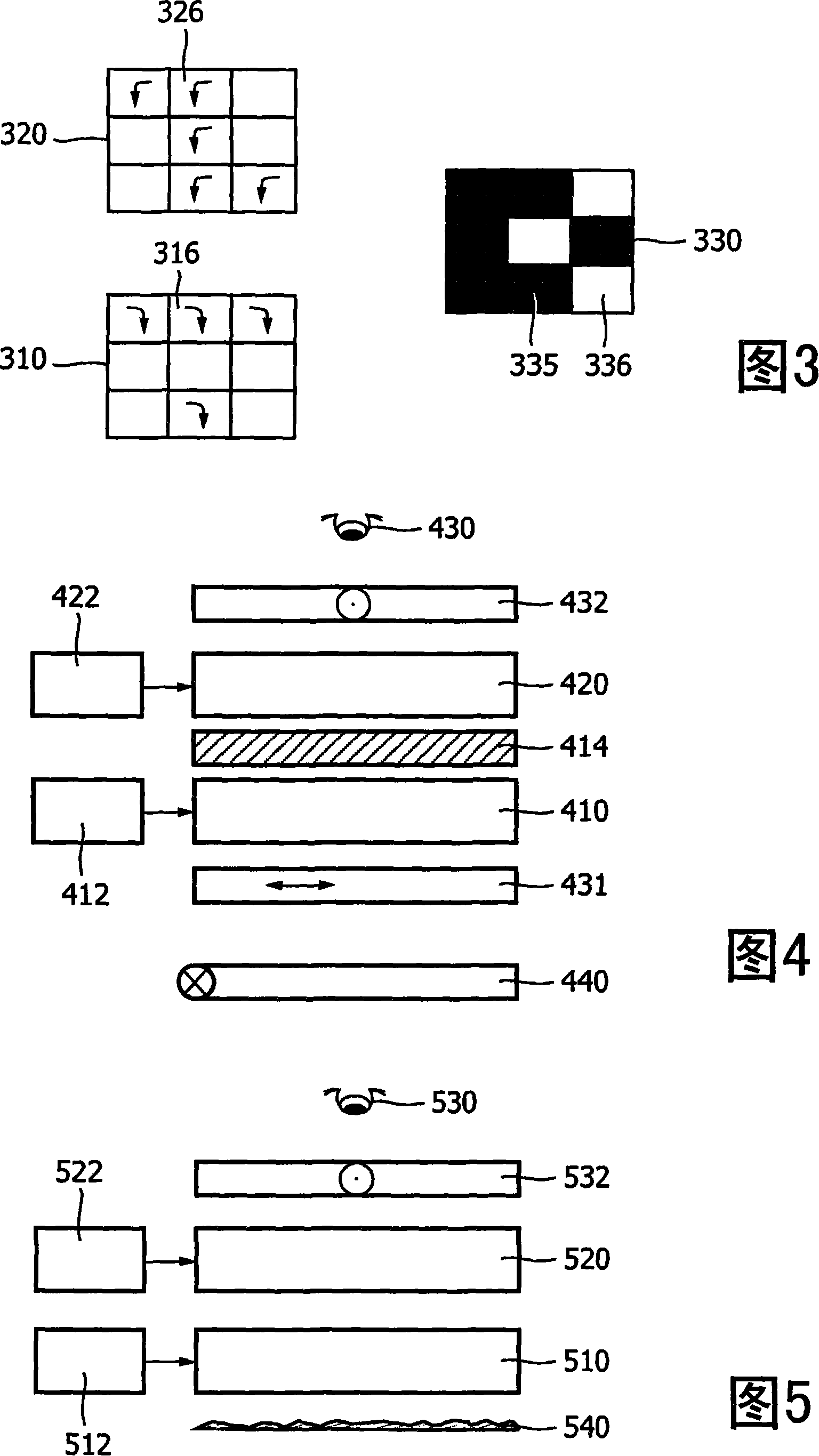
The invention relates to a display device for visually reconstructing an image (330) from an encoded image (320), such a device being particularly useful in the field of visual cryptography. The display device has two stacked liquid crystalline layers (410, 420) with individually addressable pixels. One layer (420) renders encoded image data together with a randomization pattern, and the other layer (410) only renders a randomization pattern. If the patterns match, the display device shows a visually reconstructed image (330) to a viewer. Means are provided for improving an optical match between the LC layers, such as a birefringent layer (414) between the two LC layers. Alternatively, two twisted nematic LC layers can be used having opposite twist directions. Such means were found to improve an image quality of the visually reconstructed image, and can in fact be advantageously applied in any display system including a plurality of LC layers cooperating for forming an image.

Description

technical field [0001] The invention relates to a display device for visually reconstructing an image from an encoded image. Such devices are especially useful in the field of visual cryptography. Background technique [0002] The visual cryptography system can be briefly described as follows. The image is divided into two random parts, the first part contains an encoded image, which is preferably the original image plus the random pattern, and the second part contains only the random pattern. Neither part contains identifiable information about the original image. However, when the encoded image and the matching random pattern are combined together in an appropriate device, the original image can be visually reconstructed. [0003] If non-matching parts are combined, ie two parts with non-matching random patterns, then no information about the original image is leaked and a random image is displayed on the device. If two parties want to communicate using visual cryptogr...

Claims


Application Information

Patent Timeline
IPC IPC(8): H04K1/02G02F1/13G02B5/00
CPCG09C5/00G02F1/13471G02F1/1335G02F1/1347H04K1/02G02B5/00
Inventor A·G·H·维胡尔斯特M·T·约翰逊
Owner KONINKLIJKE PHILIPS ELECTRONICS NV
Learn More