Entering bank note treating mechanism

A banknote processing and banknote technology, applied in the field of banknote processing mechanism, can solve problems such as paper jams, banknote jams, and transportation obstacles

Inactive Publication Date: 2007-12-12
OKI ELECTRIC IND CO LTD
View PDF1 Cites 30 Cited by
  • Summary
  • Abstract
  • Description
  • Claims
  • Application Information

AI Technical Summary

Problems solved by technology

[0004] However, in the above-mentioned prior art, since the optical sensor that detects the front end of the banknote is used to detect the inclination and double sheets of the banknote when the banknote is sent out, if the banknote with wrinkles (called crumpled banknotes)
) does not cause inclination, et

Method used


Image

  • Entering bank note treating mechanism
  • Entering bank note treating mechanism
  • Entering bank note treating mechanism

Examples


Embodiment 1

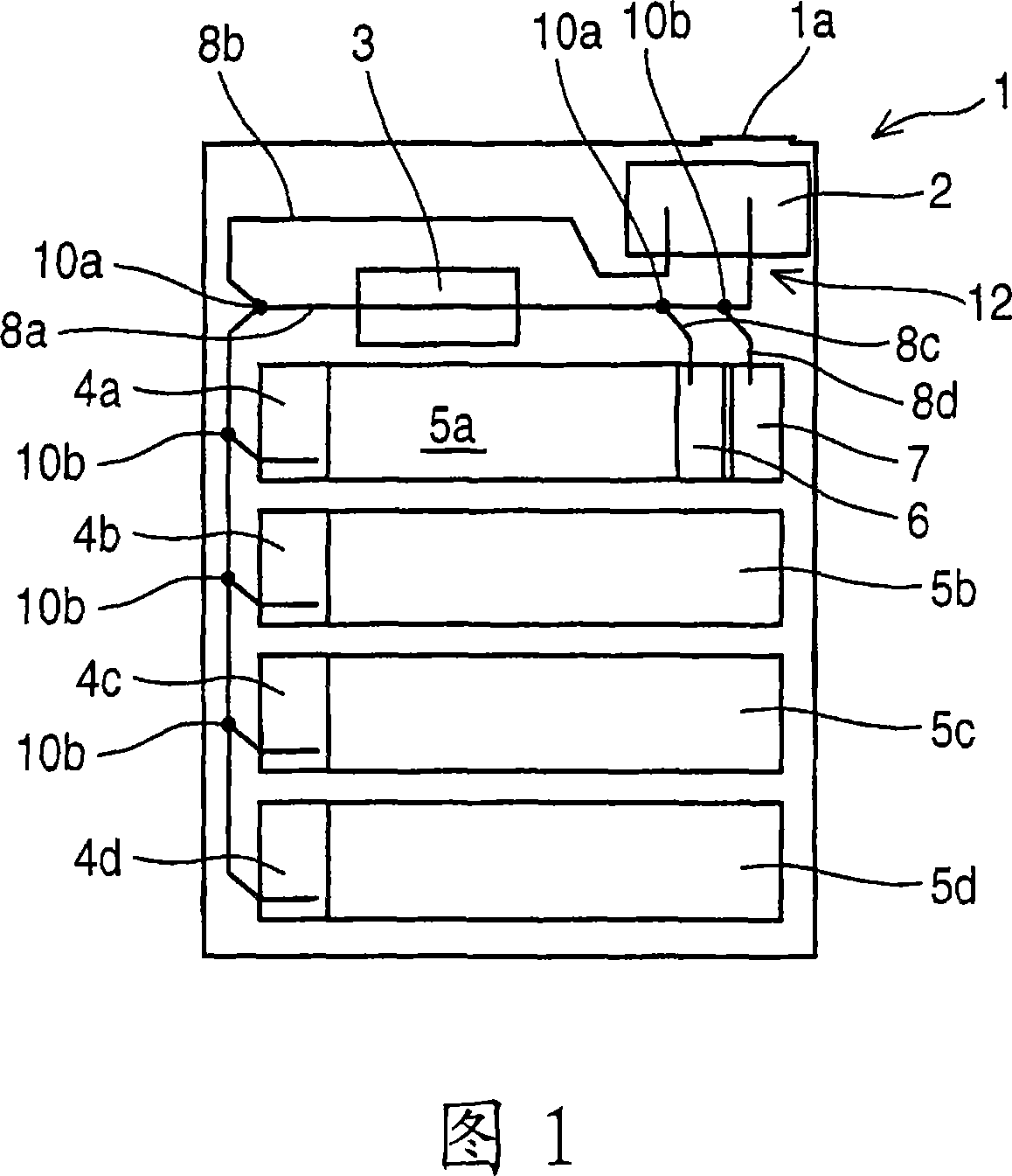
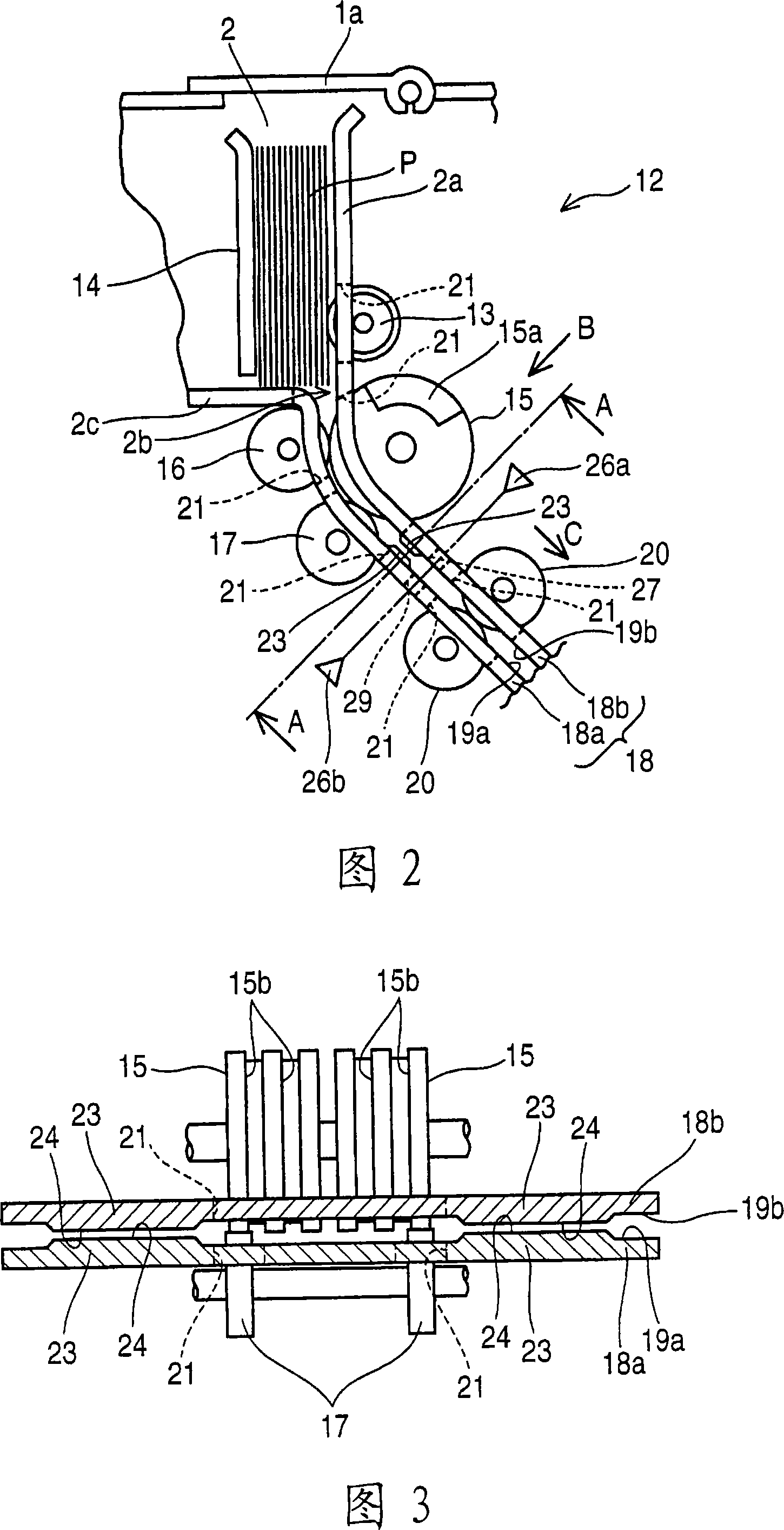
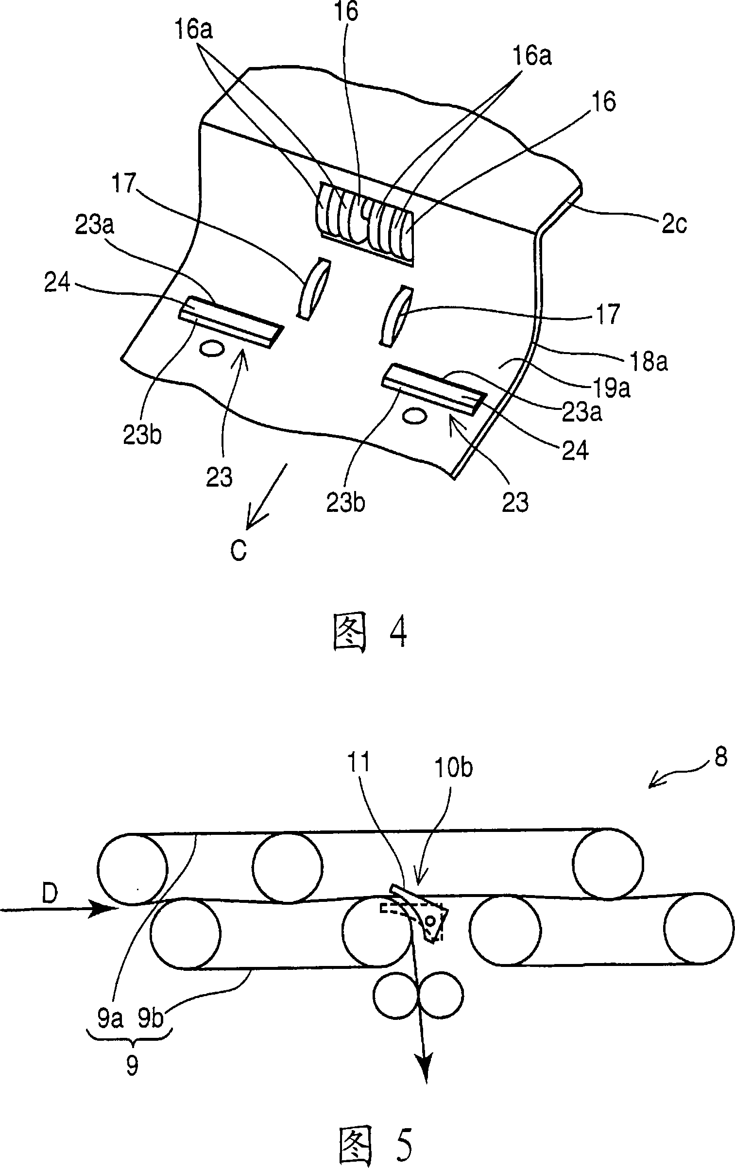
[0025] Fig. 1 is a schematic side view showing the internal structure of the banknote depositing and withdrawing device of Embodiment 1, Fig. 2 is an explanatory view showing the side of the banknote processing mechanism of Embodiment 1, and Fig. 3 is a diagram showing the A-A section in Fig. 2 Explanatory diagrams, FIG. 4 is a perspective view showing the first conveyance guide of Embodiment 1, FIG. 5 is an explanatory diagram showing the side of the branch portion of the conveyance path of Embodiment 1, and FIG. 6 shows switching of the branch portion of Embodiment 1. Stereo view of the blade.

[0026] In addition, FIG. 4 is a perspective view of the first conveyance guide seen from the B direction in FIG. 2 .

[0027] In Fig. 1, 1 is the banknote input and output device, which is provided with the following parts: the input and output banknote 2, which is used for customers to insert banknotes P or deliver banknotes P to customers; The upper part of the mouth 2 is opened a...

Embodiment 2

[0090] Fig. 10 is an explanatory diagram showing a side surface of a deposited banknote handling mechanism according to the second embodiment.

[0091] In addition, the same reference numerals are used for the same parts as in the first embodiment described above, and their descriptions are omitted.

[0092] The conveyance surface 19a of the first conveyance guide 18a of the present embodiment is formed so that the surface facing the delivery roller 15 covers the concave curved surface of the delivery roller 15. The above-mentioned concave curved surface is described by switching the blade 11 in the first embodiment. On the conveyance surface 19a that becomes this concave curved surface, on the downstream side of the nip portion formed by the delivery roller 15 and the gate roller 16, a truncated pyramid with an upstream inclined surface 23a and a downstream inclined surface 23b is provided in the same manner as in Example 1. Shaped protrusion 23 .

[0093] The protruding por...

Embodiment 3

[0099] Fig. 11 is an explanatory diagram showing a side surface of a deposited banknote handling mechanism according to the third embodiment.

[0100] In addition, the same reference numerals are used for the same parts as in the first embodiment described above, and their descriptions are omitted.

[0101] The protruding parts 23 of the present embodiment are arranged in a position staggered in the feeding direction, and the protruding parts 23 provided on the conveying surface 19a of the first conveying guide 18a are compared with the protruding parts 23 provided on the conveying surface 19b of the second conveying guide 18b. The protruding portion 23 is arranged on the upstream side.

[0102] Moreover, the position of the arrival detection sensor 26 is arrange|positioned at the downstream side along the conveyance line of the protrusion part 23 formed in the 2nd conveyance guide 18b, and is arrange|positioned at the same position as Example 1 mentioned above.

[0103] Acco...


PUM


Abstract

The invention provides an entering-paper currency treatment mechanism, which checks whether the rugate paper currency is suitable to be sent into device. The entering-paper currency treatment mechanism comprises: passageway (2) of paper currency (P); and sending foller (15), which sends the paper currency (P) out by positive rotation and receives the paper currency (P) in by negative rotation. The entering-paper currency treatment mechanism also comprises: a pair of guiding elements (18), which guides the paper currency (P) from the passageway between the opposite transport surfaces (19a, 19b); and bulge part (23) extending from the transport surfaces on the low part of the sending foller. A reaching sensor (26) is located on the low part of the bulge part (23) to check the front of the paper currency (P) when the back of the paper currency (P) not leave the passageway.

Description

technical field [0001] The invention relates to a banknote processing mechanism used in a banknote depositing and withdrawing device assembled in a cash deposit and withdrawal machine (ATM) or the like. Background technique [0002] The banknote processing mechanism used in the existing banknote depositing and withdrawing device is provided with a delivery roller at the banknote inlet for receiving banknotes. The delivery roller sends the banknotes from the banknote inlet through forward rotation, and returns the banknotes to the banknote inlet through reverse rotation. Before the rear end of the banknote sent out on the guide plate by the delivery roller leaves the delivery roller, the inclination of the banknote and the double sheet (referring to more than two banknotes being sent out at the same time) are checked by means of an optical sensor that detects the front end of the banknote. state.), when detecting the tilt or double sheets, reverse the delivery roller to retur...

Claims


Application Information

Patent Timeline
IPC IPC(8): G07D11/00B65H3/06B65H7/06
CPCG07D11/16G07D2211/00G07F19/201
Inventor 越田嘉范
Owner OKI ELECTRIC IND CO LTD
Why Eureka
Try Eureka