Input-gain control apparatus and method

A gain control, equipment technology, applied in the direction of gain control, amplification control, non-control loop limiting amplitude, etc.

Inactive Publication Date: 2007-12-12
SAMSUNG ELECTRONICS CO LTD
View PDF0 Cites 2 Cited by
  • Summary
  • Abstract
  • Description
  • Claims
  • Application Information

AI Technical Summary

Problems solved by technology

Therefore, the output is distorted

Method used


Image

  • Input-gain control apparatus and method
  • Input-gain control apparatus and method
  • Input-gain control apparatus and method

Examples


Embodiment Construction

[0036] Certain exemplary embodiments of the present invention will be described in more detail with reference to the accompanying drawings. Throughout the drawings, like reference numerals will be understood to refer to like elements, features, and structures.

[0037] The matters defined in the description, such as detailed configuration and elements, are merely provided to assist in a comprehensive understanding of the contents of the present invention. Accordingly, those of ordinary skill in the art will recognize that various changes and modifications of the exemplary embodiments described herein can be made without departing from the spirit and scope of the invention. Also, well-known functions or constructions are omitted from descriptions for clarity and conciseness.

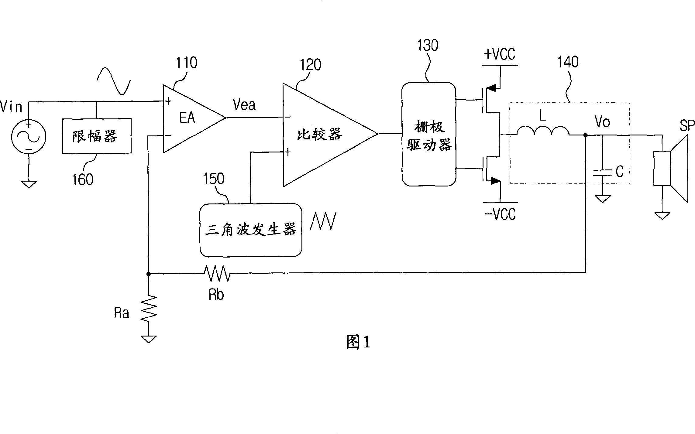
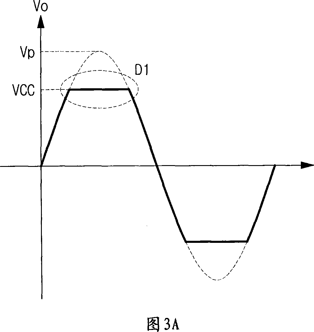
[0038] An aspect of the invention is to attenuate excess input signal to prevent clipping distortion D1 due to excess input, excess output and step-shaped high-frequency distortion D2 due to saturation o...


PUM


Abstract

Provided are input-gain control apparatus and method of an audio amplifier. A gain of an acoustic signal is automatically attenuated based on a pre-set limited level to minimize distortion of the acoustic signal caused by clipping of the acoustic signal, and thereby limit an over-input of the acoustic signal to input the acoustic signal within a dynamic range if the acoustic signal is not input within the dynamic range in an audio apparatus including an acoustic amplifier and a switching amplifier. Thus, only a gain of an over-input signal on a specific level or more can be attenuated while an original form of the over-input signal is maintained to minimize distortion of an output waveform caused by clipping of the output waveform. Also, a harmonic distortion and a stepped high frequency noise occurring during clipping can be simultaneously removed.

Description

technical field [0001] The invention relates to an input gain control device and method of an audio amplifier. More particularly, the present invention relates to an input gain control apparatus and method of an audio amplifier, in an audio apparatus including an acoustic amplifier and a switching amplifier, if an acoustic signal is not input within a dynamic range, the apparatus and method are based on a priori The set limit level automatically cuts the gain of the acoustic signal to minimize the distortion of the acoustic signal due to the clipping of the acoustic signal, and limits the excessive input of the acoustic signal to input the acoustic signal within the dynamic range. Background technique [0002] Typically, an analog-to-digital (A-D) class-D amplifier circuit performs pulse-width modulation (PWM) on an acoustic signal to convert the acoustic signal into a digital signal type, amplifies the digital signal, and passes the amplified digital signal through a low-pa...

Claims


Application Information

Patent Timeline
Patent Type & Authority Applications(China)
IPC IPC(8): H03G3/20H03G1/04
CPCH03G11/002H03G3/3026H03G7/001H03F3/217
Inventor 金成祐金允龙金湳寅
Owner SAMSUNG ELECTRONICS CO LTD
Why Eureka
Try Eureka