
Method for cutting brittle material substrate and substrate cutting system

A brittle material substrate and substrate technology, which is applied in the processing of insulating substrates/layers, nonlinear optics, stone processing equipment, etc. The effect of simplifying the process

Inactive Publication Date: 2007-12-12
MITSUBOSHI DIAMOND IND CO LTD
View PDF1 Cites 18 Cited by
  • Summary
  • Abstract
  • Description
  • Claims
  • Application Information

AI Technical Summary

Problems solved by technology

When breaking the mother boards G1 to G3 by applying a load greater than the load F, a large impact is applied, and damage such as chipping is likely to occur on the cut surface (the second direction cut surface) of the mother board G.
[0016] On the other hand, it is desirable to form the first scribe line S1 with a deep crack 1 , S1 2 In this case, it is necessary to reduce the moving speed of the laser beam or increase the laser output, but there are problems in practical use: the moving speed of the laser beam cannot be ensured sufficiently, or the quality of the truncated surface after fracture is greatly reduced

Method used


Image

  • Method for cutting brittle material substrate and substrate cutting system
  • Method for cutting brittle material substrate and substrate cutting system
  • Method for cutting brittle material substrate and substrate cutting system

Examples


Embodiment

[0113] In the case of carrying out the cutting method of the present invention as described above, it is necessary to form a trigger crack for breaking on the mother substrate when the scribing step is performed. Hereinafter, based on the experimental data, the presence or absence of the occurrence of the trigger crack for fracture will be described.

[0114] 7 shows the moving speed of the laser beam (row direction data in FIG. 7 ) when the scribing process (first scribing) is performed in the first direction, and the scribing process (second scribing) is performed in the second direction, respectively. ) data on the visible crack generation range when the laser beam moving speed (the column direction data in FIG. 7 ) is changed. The moving speeds of the laser beams for both the first scribe line and the second scribe line were changed within a range of 90 to 160 mm / s.

[0115] The material of the substrate used at this time was soda glass, and its thickness was 2.8 mm. The...


PUM

PropertyMeasurementUnit
thicknessaaaaaaaaaa

Abstract

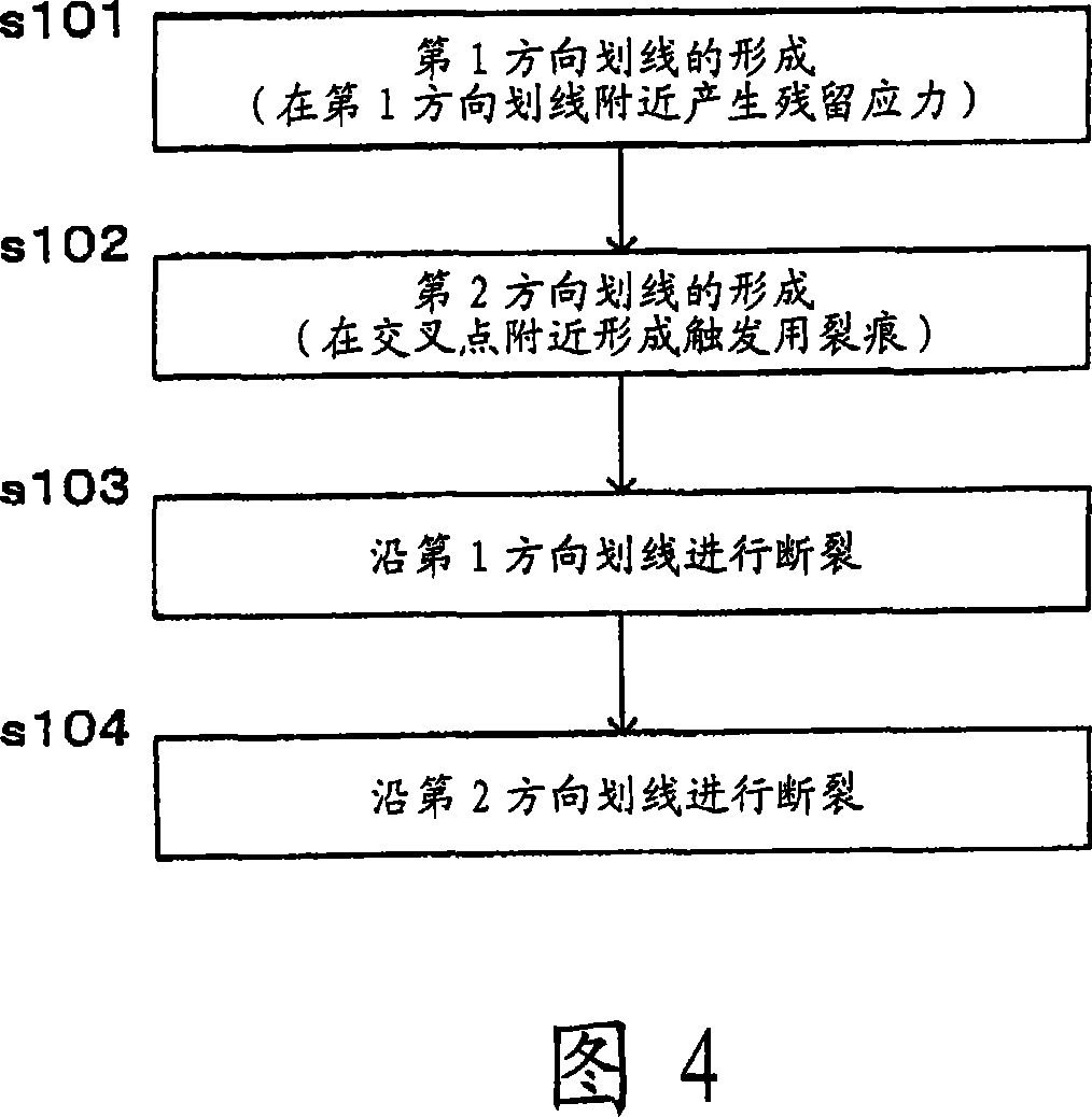
A cutting method by which an excellent substrate cut plane can be provided without generating damages such as chipping on a brittle material substrate. The substrate is broken with a breaking trigger crack as a starting point by performing (a) a first direction scribing process wherein volume contraction is locally generated near a first direction scribe line at the time of forming the first direction scribe line, relative moving speed and / or output of a laser beam is adjusted to generate a tensile stress at such portion, and scribing is performed; (b) a second direction scribing process wherein the breaking trigger crack to be the starting point of breaking in a second direction is locally formed near a cross point of the first direction scribe line and a second direction scribe line, by using the tensile stress generated near the first direction scribe line, at the time of forming the second direction scribe line; (c) a first direction breaking process for breaking the substrate along the first direction; and (d) a second direction breaking process for breaking the substrate in the second direction after the first direction breaking process.

Description

technical field [0001] The present invention relates to the use of laser beams to heat mother substrates composed of brittle materials such as glass, ceramics of sintered materials, single crystal silicon, sapphire, semiconductor wafers, and ceramic substrates at a temperature below the melting temperature, thereby forming scratches composed of vertical cracks A method for cutting a brittle material substrate and a cutting system for cutting it after the line, in particular, it relates to a method for cutting a brittle material substrate after forming vertical cracks in two directions intersecting with each other on the brittle material substrate, and cutting along these two directions, and Substrate cutting system. Background technique [0002] Conventionally, a cutter wheel or the like is pressed against a brittle material substrate while being rotated to form a scribe line, and the substrate can be cut by pressing in a vertical direction along the formed scribe line to br...

Claims


Application Information

Patent Timeline
Patent Type & Authority Applications(China)
IPC IPC(8): B28D5/00B23K26/00B23K26/08C03B33/037C03B33/09H01L21/301B23K26/364B23K101/40G02F1/13G02F1/1333
CPCB28D5/0011B65G2249/04H01L21/67092H05K2201/0909C03B33/0222B23K26/4075H05K2203/302C03B33/033H01L21/67282H05K3/0029H05K2201/09036H05K3/0052H05K1/0306C03B33/091C03B33/093B23K26/40B23K2103/50Y02P40/57B23K26/38H01L21/30
Inventor 上野勉音田健司山本幸司
Owner MITSUBOSHI DIAMOND IND CO LTD
Learn More