
Substrate surface treating apparatus

A substrate surface and processing device technology, applied in the direction of gaseous chemical plating, coating, electrical components, etc., can solve problems such as difficult to obtain thin films, achieve roughly uniform temperature, stable high-temperature heating effect, and highly homogeneous surface treatment Effect

Inactive Publication Date: 2007-12-12
M WATANABE CO LTD
View PDF1 Cites 2 Cited by
  • Summary
  • Abstract
  • Description
  • Claims
  • Application Information

AI Technical Summary

Problems solved by technology

As a result, it is difficult to obtain the desired thin film on the silicon substrate S

Method used


Image

  • Substrate surface treating apparatus
  • Substrate surface treating apparatus
  • Substrate surface treating apparatus

Examples


Embodiment Construction

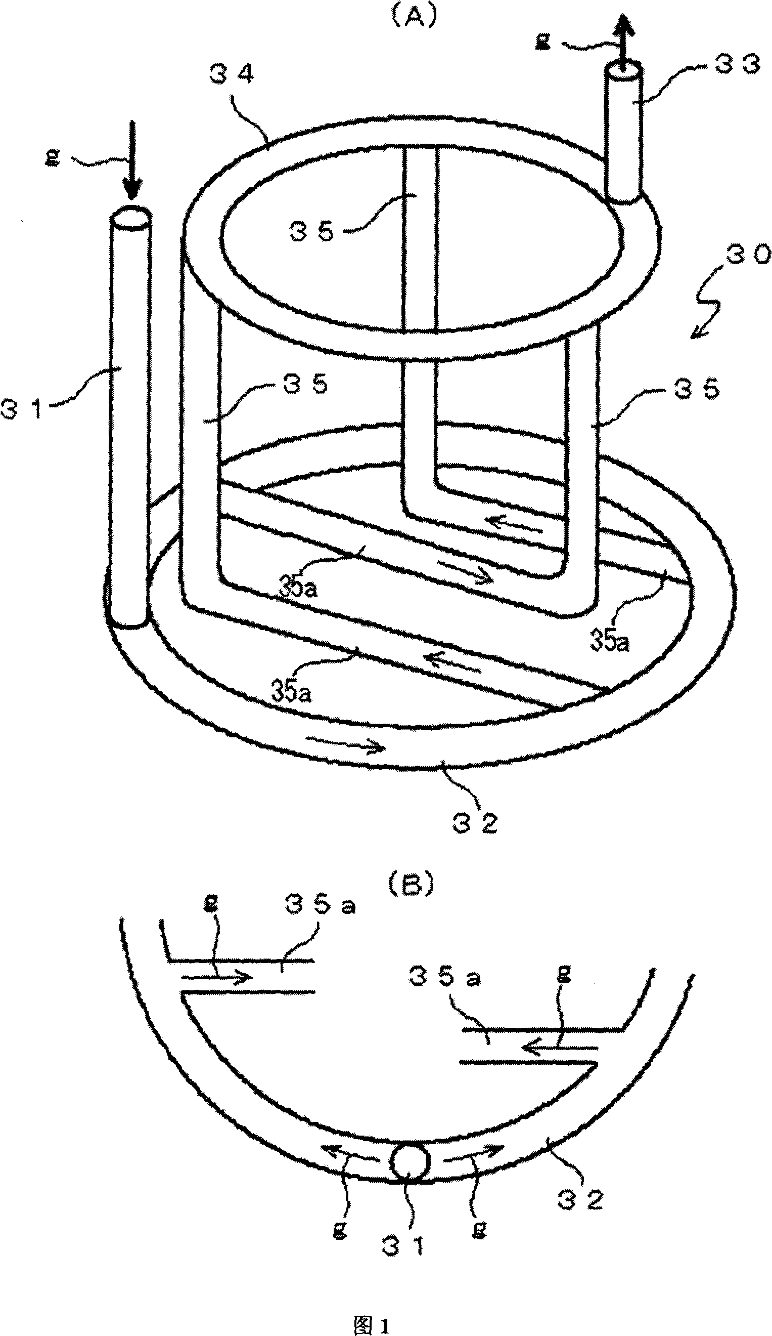
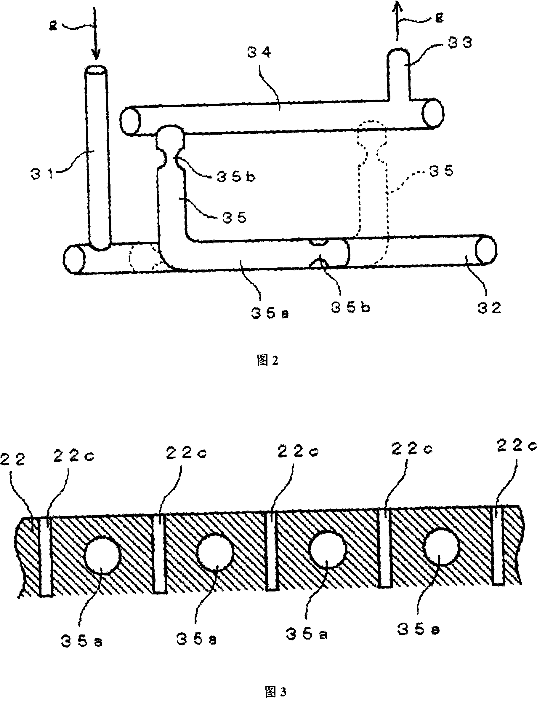
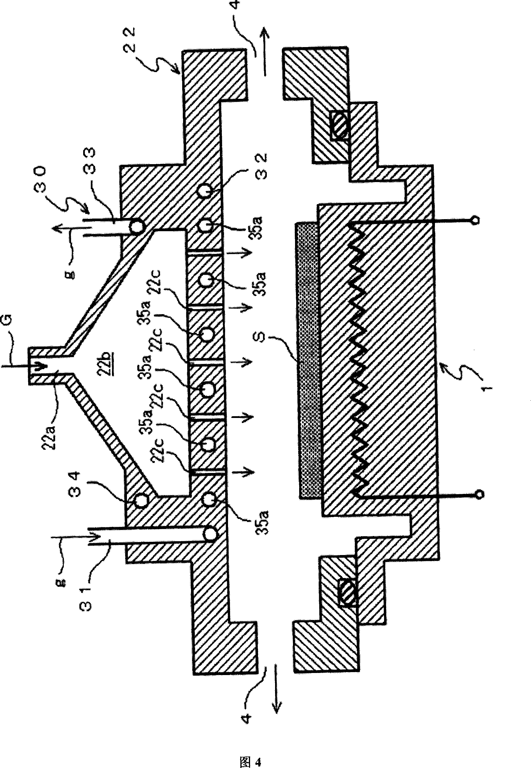
[0045] Embodiments of the substrate surface treatment apparatus according to the present invention will be described in detail with reference to the following drawings. Embodiments of the silicon substrate surface treatment apparatus of the present invention are shown respectively with reference to FIGS. 1 to 4 .

[0046] Discussion of problem points

[0047] If the object is in the shape of a disc, the greater the distance between the heat conduction path passing through the central axis and from the center to the periphery, generally, the less heat energy received from the heat source. Therefore, for this embodiment adopting several heat conduction paths, it is necessary to adjust the heat medium flow rate of each heat conduction path one by one. Moreover, the flow rate can be adjusted appropriately according to the experiment.

[0048]In addition, in FIG. 6 of Case 2 of the old model, a plurality of heat conduction paths 12b for heat medium are ensured in the gas nozzle p...


PUM


Abstract

A substrate surface treating apparatus by which the temperature of a carrier gas can be increased high and thus treatment can be more uniformly performed. An upstream ring is connected to a heating medium inlet for applying a prescribed heating medium, and a downstream ring is connected to a heating medium outlet for ejecting the heating medium. A plurality of heat transmitting paths are connected to the upstream ring and the downstream ring by having flow directions of the adjacent heating medium reaching the downstream ring from the upstream ring are opposite, and a gas is used as the heating medium.

Description

technical field [0001] The present invention relates to a substrate surface treatment device, for example, a substrate surface treatment device for performing surface treatment on the substrate surface of a silicon substrate, a synthetic semiconductor substrate, a glass substrate, etc. by spraying a carrier gas onto the substrate surface. Background technique [0002] Patent document: JP-P11-80959 Gazette [0003] Substrate surface treatment equipment is used in semiconductor-related industries to process equipment for cleaning, oxidation, and thin film deposition on the surface of semiconductor substrates. In addition, in glass-related industries, it is also used for surface treatment of products such as liquid crystal displays and plasma displays. [0004] For example, FIG. 5 is a vertical cross-sectional view showing the structure of the MOCVD chamber of the silicon substrate surface treatment apparatus of Conventional Example 1. FIG. [0005] In FIG. 5, a silicon subst...

Claims


Application Information

Patent Timeline
Patent Type & Authority Applications(China)
IPC IPC(8): H01L21/205C23C16/44H01L21/304
CPCC23C16/4557H01L21/67109C23C16/45565
Inventor 梅田优
Owner M WATANABE CO LTD
Learn More