Elevator device

A technology for elevators and equipment, applied in elevators, transportation and packaging, etc., can solve the problems of inability of micro-motion control, stop state, secondary damage and so on

Active Publication Date: 2007-12-19
HITACHI LTD +1
View PDF2 Cites 17 Cited by
  • Summary
  • Abstract
  • Description
  • Claims
  • Application Information

AI Technical Summary

Problems solved by technology

[0010] As a result, there are problems such as P-wave initial micro-motion control cannot perform its function, and when the elevator is running, the long-scale components will come into contact with the equipment in the elevator passage and cause secondary damage. When the wave detection sensitivity is low, there is a problem that the elevator will enter a needless stop state due to a small-scale earthquake in the short distance or noise and vibration unrelated to the earthquake.
Moreover, when judging the shaking of long-scale components indirectly based on the state quantities such as the speed of building shaking, displacement, or the product of speed and displacement, it is impossible to understand the state of the increase and at

Method used


Image

  • Elevator device
  • Elevator device
  • Elevator device

Examples


Embodiment Construction

[0022] Embodiments of the present invention will be described below with reference to the drawings.

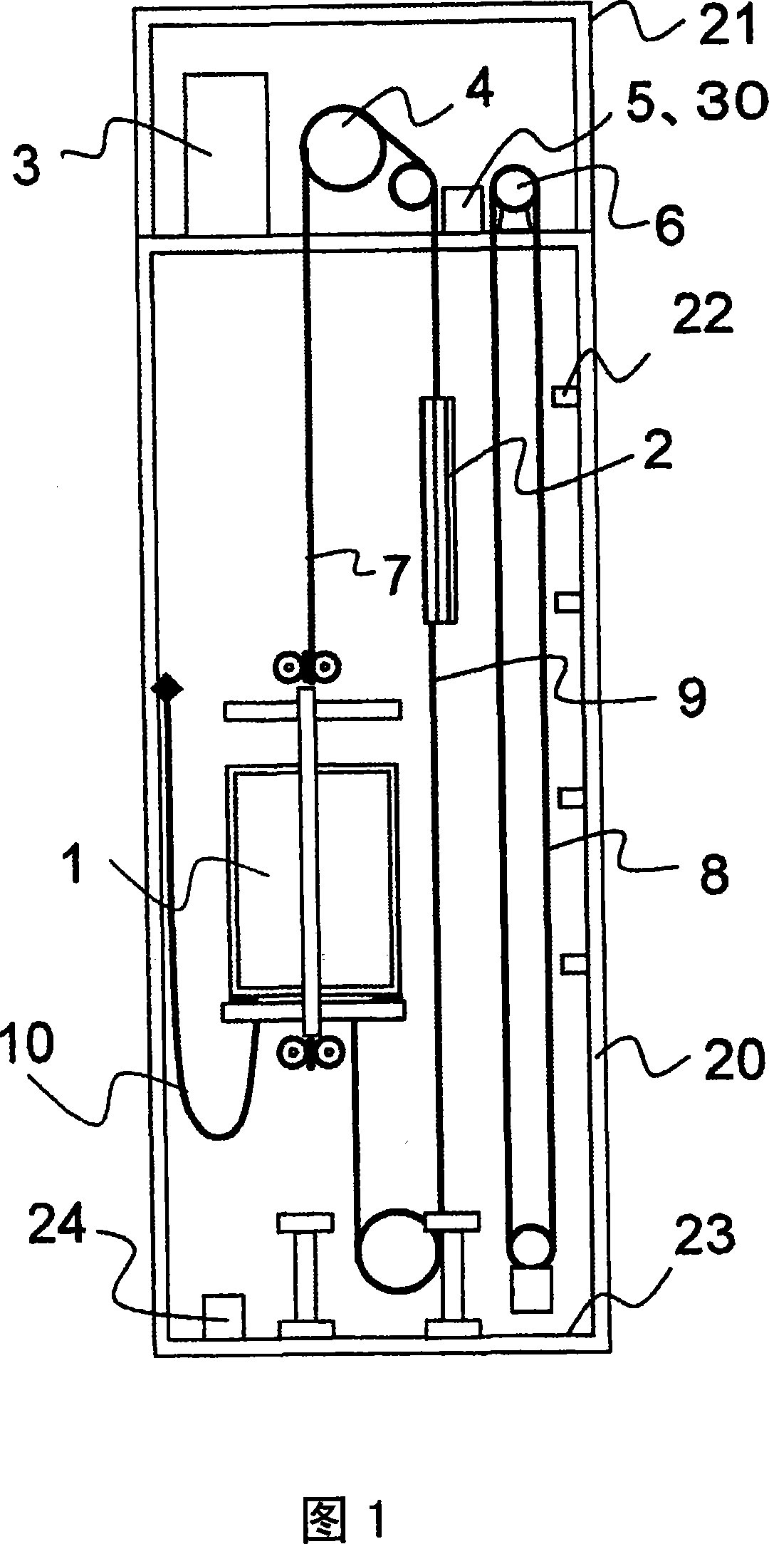
[0023] Fig. 1 is a structural schematic diagram of an elevator in an embodiment of the present invention. In the elevator system of this embodiment, the elevator car 1 is raised and lowered along a guide rail not shown, and the counterweight 2 is also raised and lowered along a guide rail not shown. Moreover, the elevator car 1 and the counterweight 2 are suspended into a bucket type by the main rope 7 passing through the hoist 4 in the machine room 21 at the top of the hoistway 20 , and are driven by the hoist 4 . Here, the control panel 3 , the governor 6 , and the vibration detector 5 are installed in the machine room 21 , and the rope 8 is wound around the governor 6 . And, viewed from the hoist side, there is provided a balance rope 9 for compensating the weight difference between the main rope 7 on the side of the elevator car 1 and the side of the counterweight 2 . Fu...


PUM


Abstract

An elevator device, which controls the operation of the elevator when an earthquake or strong wind occurs, and predicts and calculates the signal detected by the vibration detector (5) installed on the upper part of the elevator passage (20) or the upper part of the building. (20) shake responses of long-scale components such as the main sling (7) at various time points, and issue control instructions based on the calculation results. The elevator equipment of the present invention can detect vibration of long-scale components such as the main rope during earthquakes and strong winds with high precision, and perform controlled operation.

Description

technical field [0001] The present invention relates to an elevator device that performs controlled operation when a building shakes due to an earthquake or strong wind. Background technique [0002] When an earthquake occurs, the faster P-wave (longitudinal wave) and the slower-propagating S (shear wave) that exhibit the main motion of the earthquake propagate from the source to the building, respectively. As a prior art, for example, the following non-patent document 1 discloses a method of classifying the acceleration level of the S wave in the horizontal direction detected by the building shaking device into thresholds consisting of an extremely low level, a low level, and a high level. Level, and use it to control the operation of elevators during earthquakes. Before the shaking of the building due to the main motion of the S wave becomes large, the arrival of an earthquake can be detected several seconds earlier than the S wave by detecting an extremely low level of a...

Claims


Application Information

Patent Timeline
IPC IPC(8): B66B5/02
Inventor 野口直昭宫田弘市渡边春夫中山彻也重田政之
Owner HITACHI LTD
Why Eureka
Try Eureka