Beam ring force sensor

A force sensor and ring technology, applied in the field of sensors, can solve problems such as inconvenience to use, achieve high suppression ability, and overcome the effect of being susceptible to lateral force interference

Inactive Publication Date: 2007-12-19
DALIAN UNIV OF TECH
View PDF0 Cites 10 Cited by
  • Summary
  • Abstract
  • Description
  • Claims
  • Application Information

AI Technical Summary

Problems solved by technology

In order to enable the force sensor to work in an environment with a large lateral force, some auxiliary protective

Method used


Image

  • Beam ring force sensor
  • Beam ring force sensor

Examples


Embodiment Construction

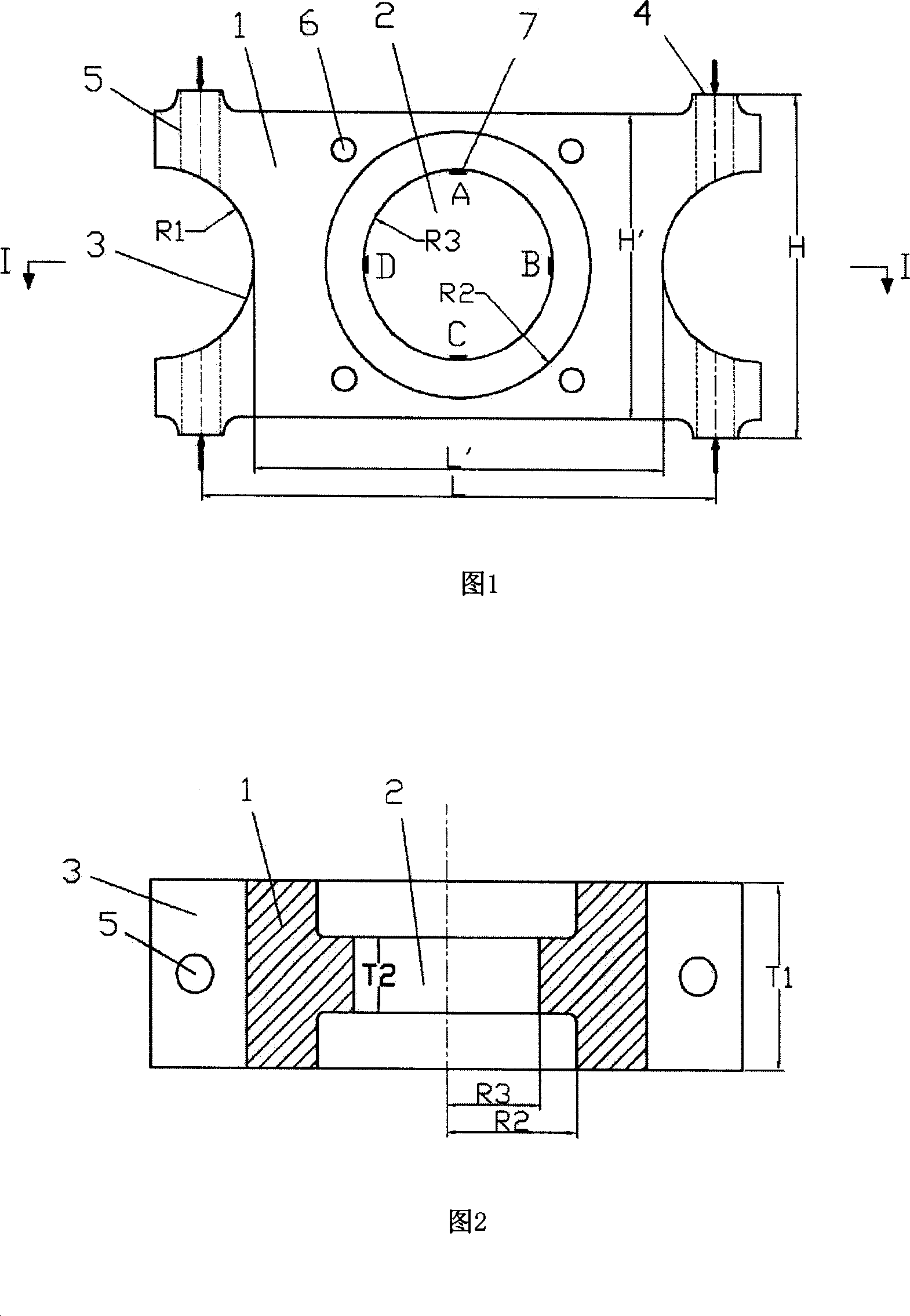
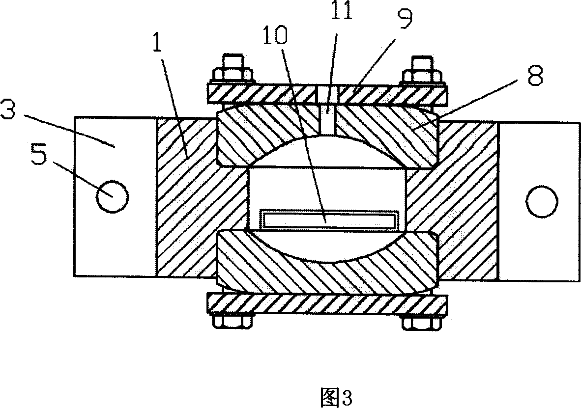
[0017] A beam-ring type force sensor of the present invention, the beam-ring type force sensor when it is not sealed is shown in Figure 1 and Figure 2, and the sensor after sealing is shown in Figure 3.

[0018] As shown in Fig. 1 and Fig. 2, a round hole 2, an arc-shaped notch 3, and a through hole 6 for fixing the pressure plate are opened on the force-bearing element 1, and a threaded hole 5 for fixing the sensor is opened on the force-bearing boss 4; L=136mm, L'=108mm, R1=25mm, R2=35mm, R3=25mm, T1=50mm, T2=20mm. The material is No. 45 steel, the sensitivity obtained by finite element calculation is 35.4με / kN 35.4με / kN, and the stiffness is 7.2×10 8 kN / m.

[0019] The sealing device is shown in Figure 3. Buckle the bowl-shaped rubber cover 8 on both sides of the round hole 2, and then press the pressure plate 9. Use four M6 bolts to fix the pressure plate on the bowl-shaped rubber cover 8 to achieve a waterproof seal. Function, wherein a set of bowl-shaped rubber cover 8...


PUM


Abstract

A force transducer of beam and ring type is prepared as applying force-bearing structure of beam and ring integrated form, using force acted on beam to cause strain value at four strain sensitive positions on internal wall of ring structure in middle to be varied, measuring out acting force size by measuring strain at four said positions, arranging concave-convex structure at internal wall of ring structure, using rubber cover to seal said transducer and using press plate to fit said rubber cover with internal surface of ring structure closely to undertake seal function.

Description

technical field [0001] The invention belongs to the technical field of sensors and relates to a force sensor. Background technique [0002] Most of the existing force sensors are strain-type force sensors, the principle of which is to convert the force signal acting on the sensor into a measurable strain signal of a certain part of the sensor itself. At present, the common forms of force measuring elements can be divided into tension and compression type (column type, cylinder type, column ring type, etc.), bending type (equal strength beam, square frame beam, square frame beam with shaped hole, etc.), Shear type (spoke type shear beam, square beam, circular section I-beam, etc.). [0003] During use, the force sensor not only bears the load from the measured force, but also bears the load from the lateral force perpendicular to the direction of the measured force. In order to reduce the influence of the lateral force on the measurement results during the use of common for...

Claims


Application Information

Patent Timeline
IPC IPC(8): G01L1/20G01L1/22
Inventor 岳前进毕祥军季顺迎屈衍
Owner DALIAN UNIV OF TECH
Why Eureka
Try Eureka