Aligned carbon nanotube films and a process for producing them

Inactive Publication Date: 2008-05-27
MITSUBISHI GAS CHEM CO INC
View PDF16 Cites 10 Cited by
  • Summary
  • Abstract
  • Description
  • Claims
  • Application Information

AI Technical Summary

Benefits of technology

[0009]An aligned film comprising carbon nanotubes having an outside diameter of 10 nm or less has go

Problems solved by technology

However, the many carbon nanotubes produced by these methods lack alignation and are unsuitable for shaping into a bundle or film.
However, these methods involve cumbersome steps for preparing the substrate on which to form aligned carbon nanotube

Method used


Image

  • Aligned carbon nanotube films and a process for producing them
  • Aligned carbon nanotube films and a process for producing them
  • Aligned carbon nanotube films and a process for producing them

Examples


Example

EXAMPLE 1

[0054]A square silica-alumina sheet that consisted of 25% silica and 75% alumina and which measured 2 mm thick and 30 mm on each side was chosen as a substrate. This substrate was dipped in Alumina Sol 200 of Nissan Chemical Industries, Ltd. as diluted 4-fold with ion-exchanged water. After 10 minutes' dipping, the substrate was recovered from the solution, dried in the air and burned at 700° C. for 5 hours. Measurement by the BET method showed that the alumina burned by the above procedure had an average pore size of 8.8 nm.

[0055]A catalyst fluid was prepared by adding 10 μL of 30% aqueous ammonia to 90 g of an aqueous solution of cobalt nitrate at a concentration of 0.2 mol / L. By addition of aqueous ammonia, the concentration of hydrogen ions in the solution changed from a pH of 4.5 to 7.2

[0056]The previously prepared alumina substrate was dipped in the catalyst fluid for 10 minutes. The substrate was recovered, air dried for 1 hour and burned at 400° C. for 3 hours in th...

Example

EXAMPLE 2

[0058]A square silica-alumina sheet that consisted of 25% silica and 75% alumina and which measured 2 mm thick and 30 mm on each side was chosen as a substrate. This substrate was dipped in Alumina Sol 200 of Nissan Chemical Industries, Ltd. as diluted 4-fold with ion-exchanged water. After 10 minutes' dipping, the substrate was recovered from the solution, dried in the air and burned at 650° C. for 5 hours. Measurement by the BET method showed that the alumina burned by the above procedure had an average pore size of 6.7 nm.

[0059]A catalyst fluid was prepared by adding 10 μL of 30% aqueous ammonia to 90 g of an aqueous solution of cobalt nitrate at a concentration of 0.2 mol / L. By addition of aqueous ammonia, the concentration of hydrogen ions in the solution changed from a pH of 4.5 to 7.2

[0060]The previously prepared alumina substrate was dipped in the catalyst fluid for 10 minutes. The substrate was recovered, air dried for 1 hour and burned at 400° C. for 3 hours in th...

Example

EXAMPLE 3

[0062]A square silica-alumina sheet that consisted of 25% silica and 75% alumina and which measured 2 mm thick and 30 mm on each side was chosen as a substrate. This substrate was dipped in Alumina Sol 200 of Nissan Chemical Industries, Ltd. as diluted 4-fold with ion-exchanged water. After 10 minutes' dipping, the substrate was recovered from the solution, dried in the air and burned at 800° C. for 5 hours. Measurement by the BET method showed that the alumina burned by the above procedure had an average pore size of 10.4 nm.

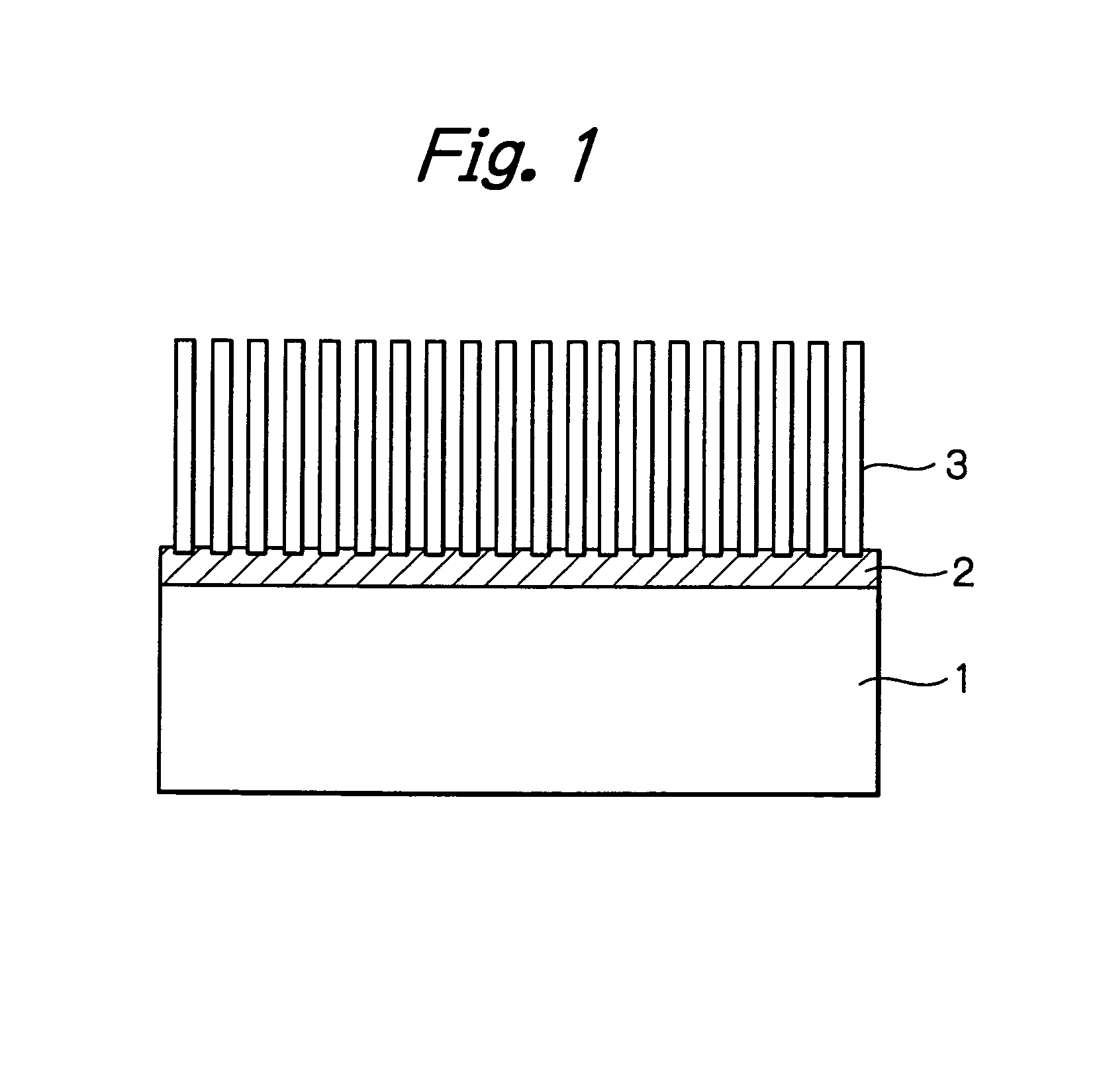
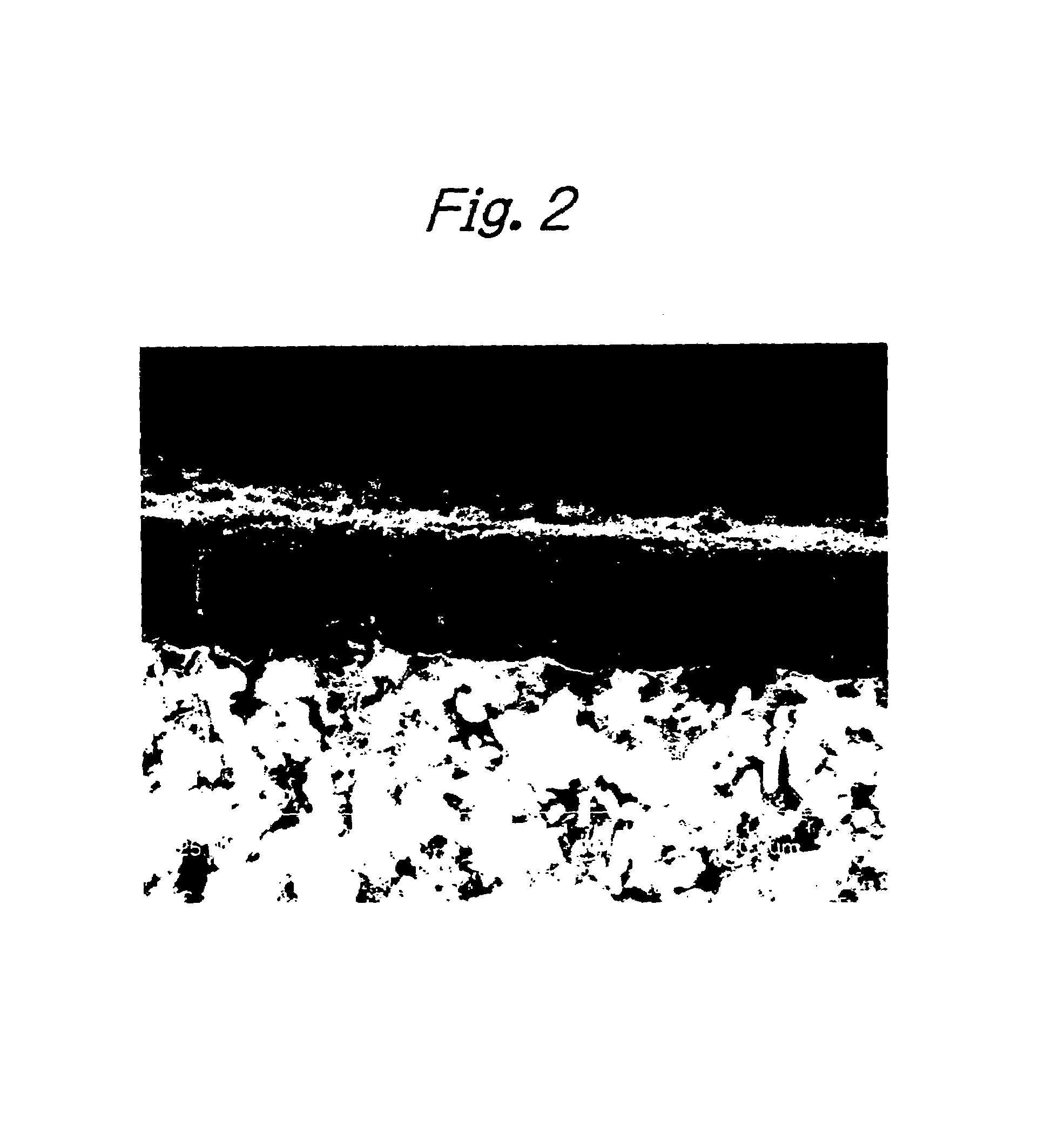
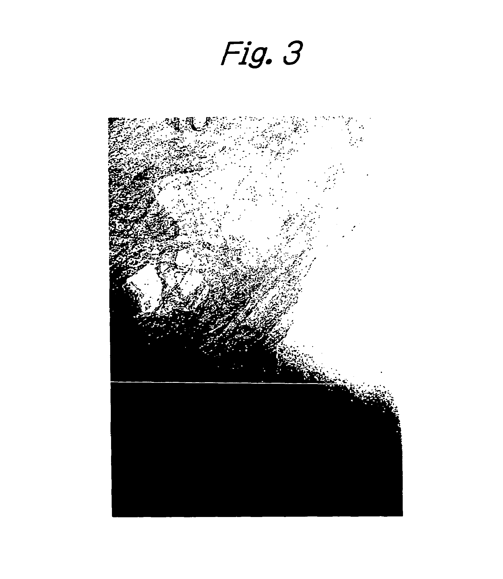
[0063]Except for the use of this substrate, preparation of a catalyst fluid, dipping of the substrate in the catalyst fluid and a reaction for producing a carbon nanotube aligned film were performed as in Example 1. After the end of the reaction, the surface of the substrate was examined with a SEM and it was confirmed that an aligned carbon nanotube film had been formed in a thickness of about 5 μm on top of the substrate. The individual carbon nanotu...


PUM


Abstract

Fine catalyst particles are loaded on a sol-gel method porous carrier having fine pores of 0.1-50 nm and a carbon compound is decomposed to form a carbon nanotube film on the carrier that is aligned perpendicular to the carrier surface. The starting sol to be processed by a sol-gel method is a dispersion of fine alumina particles, fine aluminum hydroxide particles, fine silica particles or mixtures thereof. Alternatively, the starting sol may be an aluminum alkoxide, an alkoxysilane, a mixture thereof or a solution of an aluminum alkoxide, an alkoxysilane or a mixture thereof. If desired, a flammable or a thermally decomposable organic compound may be added as a microporous template.

Description

BACKGROUND OF THE INVENTION[0001]This invention relates a process for producing an aligned carbon nanotube film comprising a large number of aligned carbon nanotubes. The process is advantageous for producing aligned carbon nanotube films that find use as electron emitters, battery electrodes, gas separation films, sensors and in energy storage.[0002]The carbon nanotube was first discovered by Sumio Iijima in 1991 (Nature, 354, pp. 56-58 (1991)). It is a carbon material, generally in the form of a very long (1-100 μm) hollow tube with a diameter of 1-100 nm. A wide range of potential applications have been proposed for the carbon nanotube and they include the use as electron emitters, battery electrodes, gas separation membranes, sensors and in energy storage. When a multiple of carbon nanotubes are to be used in these applications, the tubes are preferably aligned in one direction so that their individual features are integrated and assembled into a system in an efficient and easy ...

Claims


Application Information

Patent Timeline
IPC IPC(8): D01F9/12D01F9/127
CPCB82Y30/00D01F9/127Y10S977/843C01B32/05B82B3/00H01J9/02
Inventor SOMEYA, MASAOFUJII, TAKASHI
Owner MITSUBISHI GAS CHEM CO INC
Why Eureka
Try Eureka