
Aggregate of carbon nanotubes, dispersion thereof and conductive film using the same

a technology of carbon nanotubes and conductive films, applied in the field of carbon nanotubes, can solve the problems of difficult to exhibit a practical performance in applications as a transparent conductive film, molded article, membrane or the like using the carbon nanotube, and hinder the development of various applications. , to achieve the effect of excellent light transmittance and surface resistance, good dispersibility, and high quality

Inactive Publication Date: 2014-09-16
TORAY IND INC
View PDF22 Cites 5 Cited by
  • Summary
  • Abstract
  • Description
  • Claims
  • Application Information

AI Technical Summary

Benefits of technology

The approach results in a carbon nanotube aggregate with improved dispersibility, enabling the creation of transparent conductive films with high light transmittance and surface resistance, as well as effective electron emission characteristics.

Problems solved by technology

However, since the single-walled carbon nanotube has a strong and very thick bundle structure, it cannot exhibit a nano-effect that each carbon nanotube possesses, and it has been difficult to develop various applications thereof.
In particular, since the dispersion in a resin or solvent is difficult, its expected high characteristic cannot be exhibited, and the present situation is that the development of various applications has been hindered.
In particular, it has been difficult to exhibit a practical performance in applications as a transparent conductive film, molded article, membrane or the like using the carbon nanotube
However, a double-walled carbon nanotube with high quality forms, in the same manner as a single-walled carbon nanotube, a strong bundle through a hydrophobic interaction between tubes and interaction between pi-electrons, and it has been thought to be difficult to disperse the carbon nanotube.
Carbon nanotubes described in the foregoing documents are those produced in the same synthesis method, as described in Journal of American Chemical Society, the combustion peak temperature is as high as 717° C., it is thought that these carbon nanotubes form a strong and thick bundle, and they were not sufficient in the case where dispersibility of high level was required.
However, since such multi-walled carbon nanotubes are inferior in quality, it has been difficult to exhibit practical performance in applications as a transparent conductive film, molded article, membrane or the like requiring particularly excellent light transmittance and surface resistance.

Method used


Image

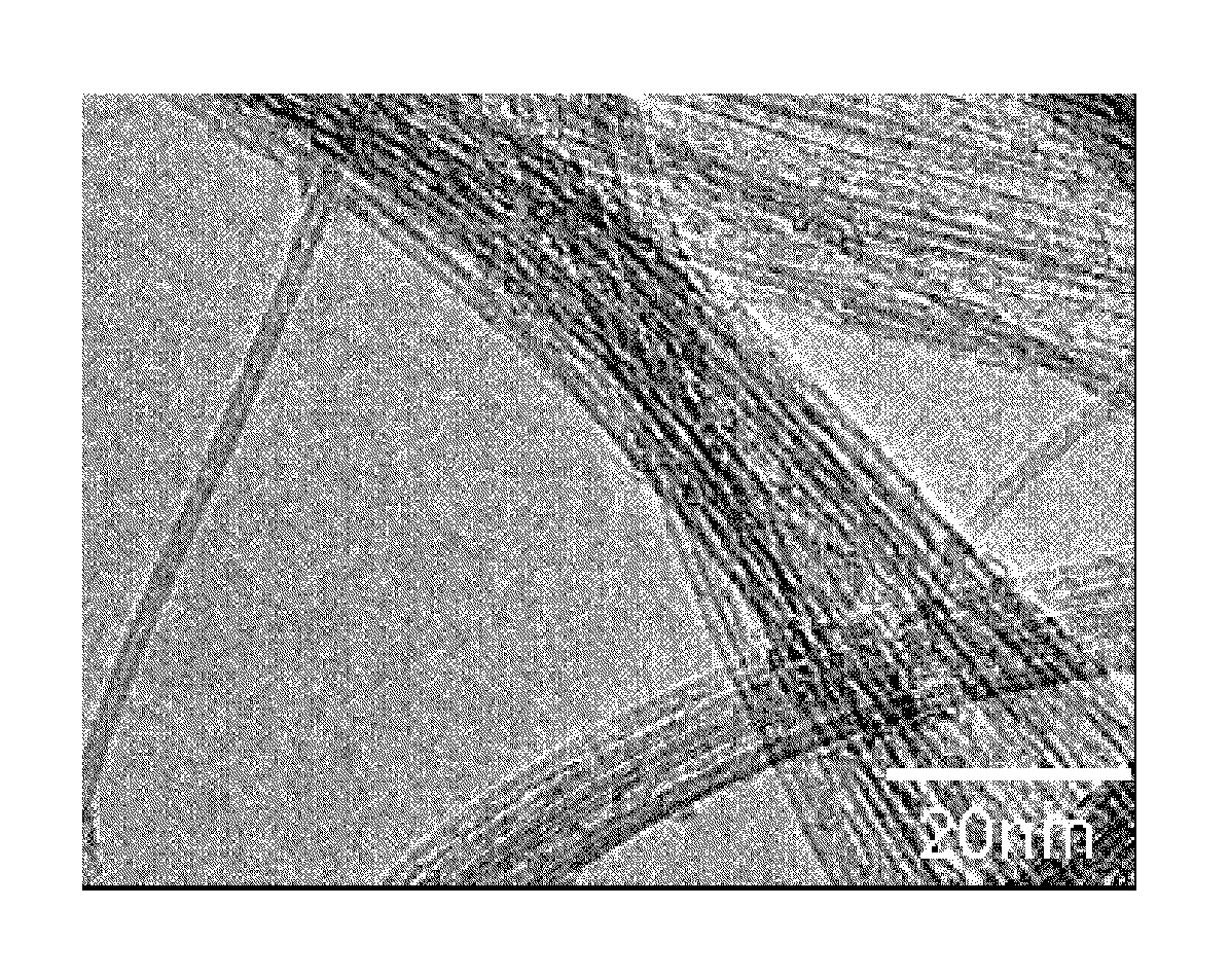
  • Aggregate of carbon nanotubes, dispersion thereof and conductive film using the same
  • Aggregate of carbon nanotubes, dispersion thereof and conductive film using the same
  • Aggregate of carbon nanotubes, dispersion thereof and conductive film using the same

Examples


example 1

Supporting Metal Salt on Light Magnesia

[0131]5 g of iron ammonium citrate (manufactured by Wako Pure Chemical Industries Ltd.) was dissolved in 250 mL of methanol (manufactured by Kanto Chemical Co., Ltd). To this solution, 50 g of light magnesia (manufactured by Wako Pure Chemical Industries Ltd., bulk density was 0.16 g / mL) was added, treated for 60 minutes by an ultrasonic cleaner, and methanol was removed while stirring at 40° C. to 60° C., thereby to obtain a solid catalyst that metal salt was supported on light magnesia powder.

[0132](Synthesis of Aggregate of Carbon Nanotubes)

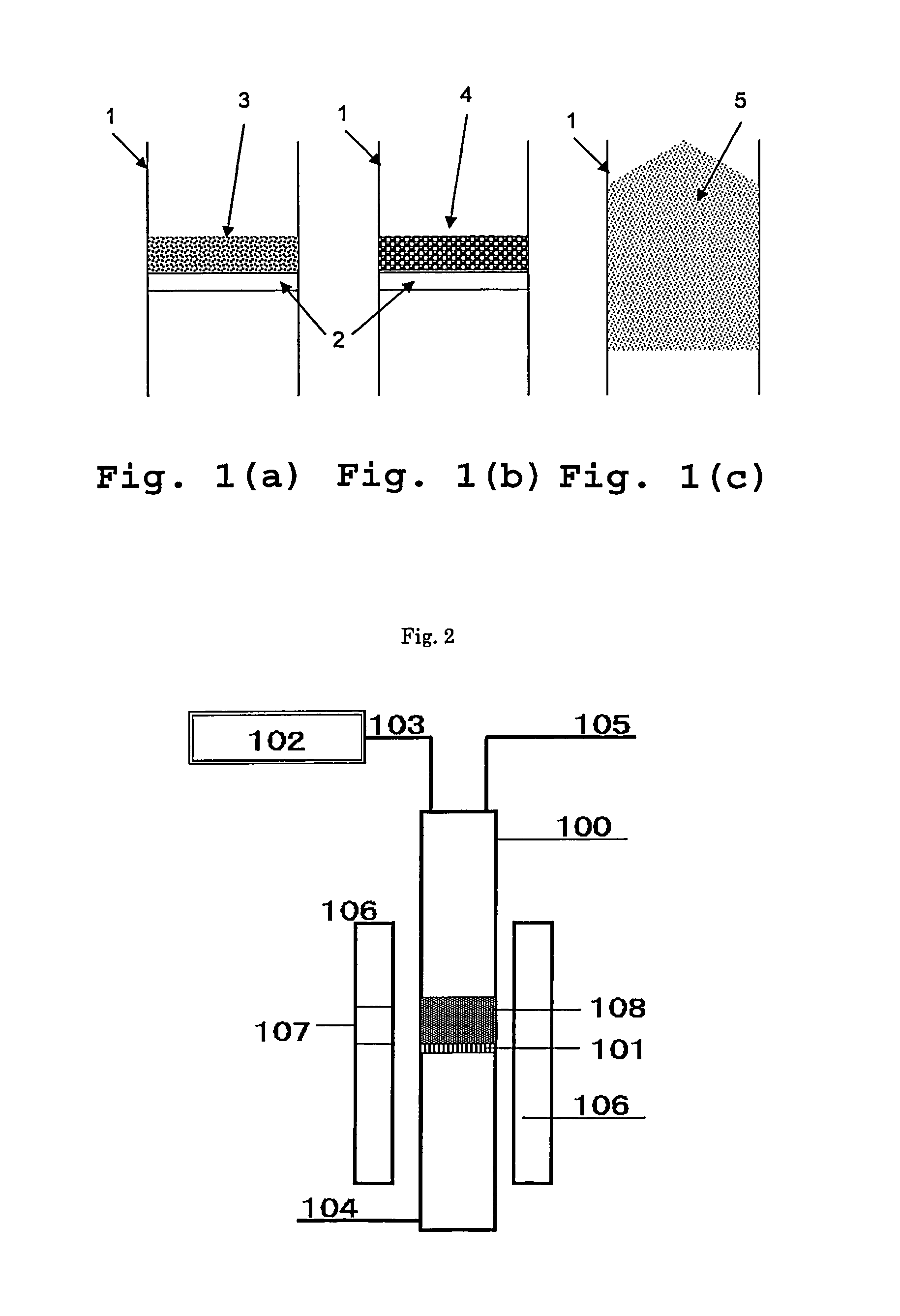
[0133]An aggregate of carbon nanotubes was synthesized by a vertical fluid bed reactor shown in FIG. 2. A reactor 100 is a cylindrical quartz tube of 32 mm in inner diameter and 1200 mm in length. A quartz sintered plate 101 was equipped in the center part, an inert gas and raw gas supply line 104 is equipped in the under part of the quartz tube, and in the upper part, a waste gas line 105 and a catalyst ...

example 2

Supporting Metal Salt on Light Magnesia

[0153]It was conducted in the same manner as in Example 1.

[0154](Synthesis of Aggregate of Carbon Nanotubes)

[0155]It was conducted in the same manner as in Example 1. Regarding the aggregate of carbon nanotubes obtained, thermal analysis was conducted, as a result, the combustion peak was 458° C.

[0156](Burning of Aggregate of Carbon Nanotubes, Purification Treatment)

[0157]30 g of the aggregate of carbon nanotubes obtained was sampled in a porcelain dish (150φ), it was raised to 410° C. over 1 hour under atmospheric pressure in a muffle furnace (FP41 manufactured by Yamato Scientific Co., Ltd.) and maintained for 60 minutes, then cooled naturally. Further, to remove the catalyst from the aggregate of carbon nanotubes, purification treatment was conducted as follows. The aggregate of carbon nanotubes obtained was added to 5N aqueous hydrochloric acid solution and stirred for one hour. A recovered material obtained by filtration using a filter of ...

example 3

Supporting Metal Salt on Light Magnesia

[0172]The same manner as in Example 1.

[0173](Synthesis of Aggregate of Carbon Nanotubes and Burning)

[0174]The same vertical fluid bed reactor as in Example 1 was used.

[0175]Catalyst of 12 g was sampled, and the catalyst was set on the quartz sintered plate 101 through the catalyst input line 103. Next, supply of nitrogen gas was started from the gas supply line 104 at 1000 mL / min. After inside of the reactor was replaced with nitrogen gas atmosphere, temperature was raised to 900° C. (rising temperature time of 30 minutes).

[0176]After temperature reached 900° C., the temperature was kept, flow rate of argon in the gas supply line 104 was increased at 2000 mL / min, fluidization of solid catalyst on the quartz sintered plate was started. After fluidization was confirmed through the inspection port 107 of heating furnace, further supply of methane was started at 95 mL / min (methane concentration of 4.5 vol %) to the reactor. After the mixed gas was ...


PUM

PropertyMeasurementUnit
diameteraaaaaaaaaa
aaaaaaaaaa
aaaaaaaaaa

Abstract

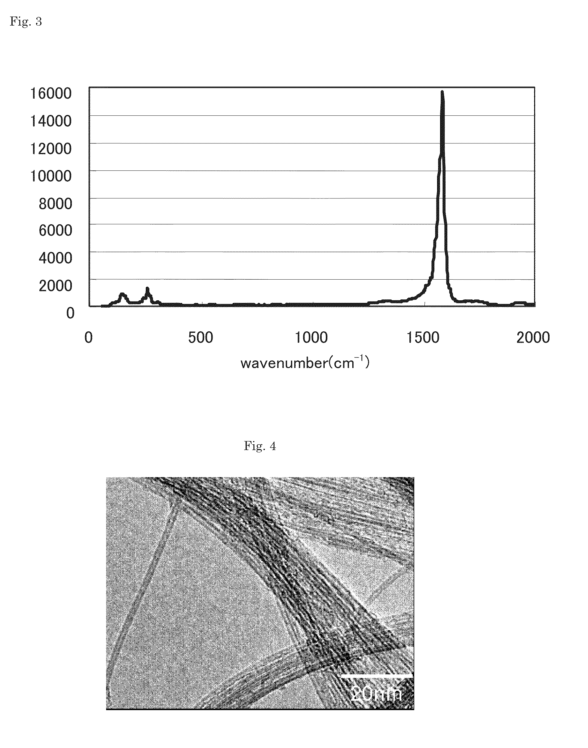
Provided is an aggregate of carbon nanotubes satisfying (1) there is a 2θ peak at 24°±2° by X-ray powder diffraction analysis; (2) a height ratio (G / D ratio) of G band to D band by Raman spectroscopic analysis of wavelength 532 nm is 30 or more; and (3) a combustion peak temperature is from 550° C. to 700° C. The present invention provides an aggregate of carbon nanotubes excellent in dispersibility while high quality, giving a film, molded article, membrane or the like having excellent characteristics.

Description

BACKGROUND OF THE INVENTION[0001]1. Field of the Invention[0002]The present invention relates to an aggregate of carbon nanotubes. Further specifically, it relates to an aggregate of carbon nanotubes and a dispersion thereof, a transparent conductive film, and a field emission material.[0003]2. Description of the Related Art[0004]In 1991, carbon nanotubes were widely reported for the first time. A carbon nanotube has a tubular shape that substantially one face of graphite is wound, one wound in one layer is called a single-walled carbon nanotube, and one wound in multilayer is called a multi-walled carbon nanotube. Among multi-walled carbon nanotubes, in particular, one wound in two layers is called a double-walled carbon nanotube. Carbon nanotubes are expected to be used as a conductive material having excellent intrinsic electrical conductivity by themselves.[0005]As a method for producing carbon nanotubes, an arc discharge method, laser evaporation method, chemical vapor depositi...

Claims


Application Information

Patent Timeline
Patent Type & Authority Patents(United States)
IPC IPC(8): D01F9/12B82Y30/00B82Y40/00C01B31/02C08J7/043C08J7/044C08J7/046C08J7/06C08K3/04C09D5/24C09D7/61H01B1/04H01B1/12H01B1/24H01J1/304
CPCD01F9/12C08J7/06C09D7/1291C08J7/047B82Y30/00H01B1/128C09D5/24B82Y40/00C01B31/0273H01B1/04H01J1/304H01B1/24C08J2400/12C01B2202/06C01B2202/28C08J2367/02H01J2201/30469C08K3/04Y10T428/30C01B32/174C09D7/70C08J7/0427C09D7/61C08J7/043C08J7/046C08J7/044
Inventor SATO, KENICHIYOSHIKAWA, MASAHITOOKAMOTO, NAOYONUMATA, SHUKO
Owner TORAY IND INC
Learn More