Discharge lamp

a discharge lamp and high ra technology, applied in the direction of discharge tube main electrodes, discharge tube luminescnet screens, gas-filled discharge tubes, etc., can solve the problems of limited service life, attenuation of irradiance, and large initial feed amount of the emitter, and achieve good electron emission characteristics, stable operation over a long time, and high radiance

Inactive Publication Date: 2005-06-23
USHIO DENKI KK
View PDF4 Cites 7 Cited by
  • Summary
  • Abstract
  • Description
  • Claims
  • Application Information

AI Technical Summary

Benefits of technology

[0014] A primary object of the present invention is to devise a discharge lamp with high radiance in which a constant feed of the emitter to the electrode tip is achieved, in which a good electron emission characteristic is maintained, and which has electrodes by which stable operation over a long time is maintained.

Problems solved by technology

However, since the emitter is vaporized from the electrode surface and is lost, to maintain a good electron emission characteristic it is necessary to add emitter.
When the amount of feed from the inside of the electrode is more dramatically reduced than the amount which is lost from the electrode tip, the service life is limited because the arc spot moves, the size of the arc spot changes, and thus the phenomenon of an unstable arc is caused.
If initially the content of emitter within the substrate metal of the electrode is increased, the initial feed amount of the emitter is too large.
The emitter which has been supplied in excess immediately vaporizes; this causes attenuation of the irradiance by initial blackening after the start of operation.
The method of increasing the content of the emitter and thus of prolonging the service life therefore has its limit.
That the amount of feed of the emitter to the electrode tip is reduced over the course of time cannot be avoided.
Therefore, it is difficult to keep the feed amount constant.
However, since the added emitter is being used up and since the path to the electrode tip is being lengthened, it is difficult to keep the feed amount constant.

Method used


Image

  • Discharge lamp
  • Discharge lamp
  • Discharge lamp

Examples


embodiment 1

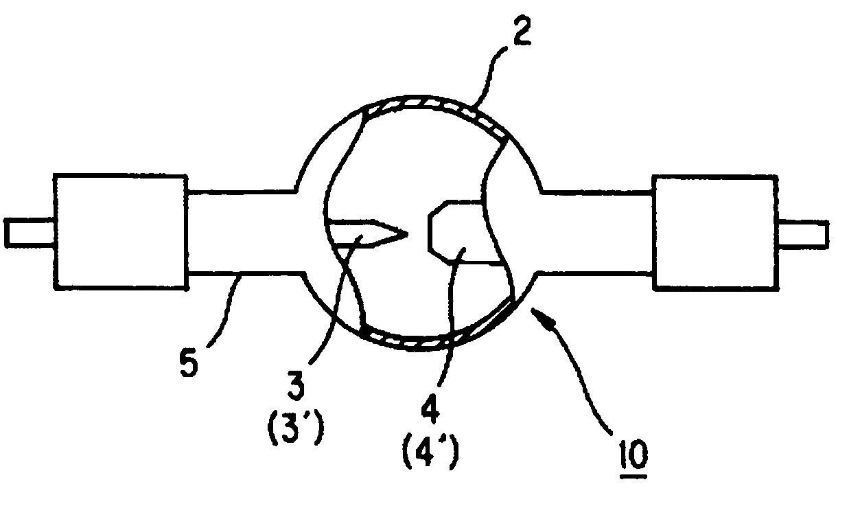
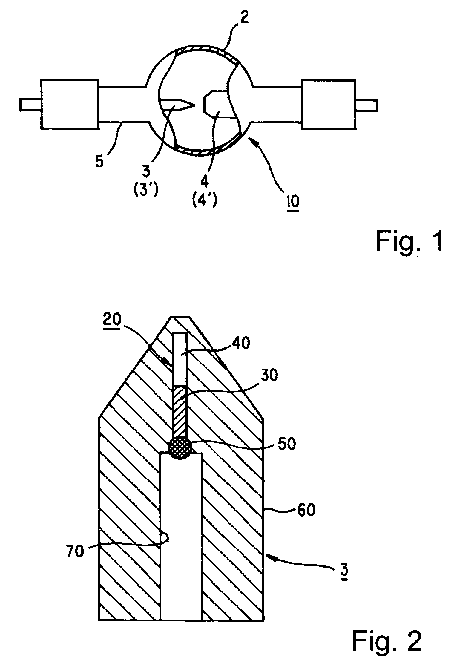
[0074] The overall shape of the lamp corresponds to FIG. 1. FIG. 2, as has been essentially described above, is an enlarged cross-section of the electrode which is operated as a cathode. A rod-like tungsten material with a diameter of 15 mm which contains lanthanum oxide with 1% by weight was used as the substrate metal with a high melting point 60. The cathode tip was worked into the shape of a truncated cone with a tip diameter of 1.2 mm and a tip angle of 80 degrees. At the point which is 1.0 mm away from the tip, there is a hermetically closed chamber 20 with a diameter of 1.0 mm and a length of 8 mm which extends down from directly underneath the tip along the lengthwise axis of the electrode. The hermetically closed chamber 20 was filled with an about 5.0 mg piece of lanthanum as the emitter 30. Enclosure was achieved by a temporary tungsten plug (not shown) which was irradiated from behind with YAG laser light and part of it was melted.

[0075] Using the above described cathod...

embodiment 2

[0078] The overall shape of the lamp corresponds to FIG. 1. The substrate metal with a high melting point 60 of the electrode which is operated as a cathode in FIG. 2 was a rod-shaped tungsten material with a diameter of 12 mm which contains lanthanum oxide with 1% by weight. The cathode tip was machined into the shape of a truncated cone with a tip diameter of 1.2 mm and a tip angle of 60 degrees. At a point which is 1.5 mm away from the tip, there is a hermetically closed chamber 20 with a diameter of 0.8 mm and a length of 20 mm which extends down from directly underneath the tip along the lengthwise axis of the electrode. The hermetically closed chamber 20 was filled with 2.0 mg lanthanum iodide as the emitter. Using the above described cathode, a super-high pressure mercury lamp with a lamp input wattage of 4.3 kW and a distance between the electrodes of 5.2 mm was produced.

[0079] In a lamp with the same shape using a conventional cathode for which tungsten which contains 2% t...

embodiment 3

[0080] The overall shape of the lamp corresponds to FIG. 1. The substrate metal with a high melting point 60 of the electrode which is operated as a cathode in FIG. 2 was a rod-shaped tungsten material with a diameter of 10 mm which contains cerium oxide with 1% by weight. The cathode tip was machined into the shape of a truncated cone with a tip diameter of 1.0 mm and a tip angle of 45 degrees. At a point 0.5 mm away from the tip there is a hermetically closed chamber 20 with a diameter of 0.6 mm and a length of 8 mm which extends down from directly underneath the tip along the electrode axis. The hermetically closed chamber 20 was filled with a roughly 5.0 mg piece of yttrium as the emitter. Using the above described cathode a super-high pressure mercury lamp with a lamp input wattage of 2.5 kW and a distance between the electrodes of 4.7 mm was produced.

[0081] In a lamp with the same shape using a conventional cathode for which tungsten which contains 2% thorium oxide, arc insta...


PUM


Abstract

A discharge lamp with high radiance in which constant feed of the emitter to the electrode tip is achieved, in which a good electron emission characteristic is maintained, and which has electrodes by which stable operation over a long time is maintained is obtained in a discharge lamp which has a translucent vessel which is hermetically closed and contains a pair of opposite electrodes that are electrically connected via hermetically sealed areas by at least one of the electrodes being made of a metal with a high melting point that has a hermetically sealed chamber that contains an emitter and a space which is not filled with the emitter.

Description

BACKGROUND OF THE INVENTION [0001] 1. Field of the Invention [0002] The invention relates to a discharge lamp with high radiance, such as a super-high pressure mercury lamp or the like. The invention relates especially to its electrodes. [0003] 2. Description of the Prior Art [0004] The electrodes of a discharge lamp with high radiance acquire a good electron emission characteristic in that an emitter, such as thorium, lanthanum, barium or the like, is adsorbed by the substrate material comprising the electrodes, and the work function is reduced. However, since the emitter is vaporized from the electrode surface and is lost, to maintain a good electron emission characteristic it is necessary to add emitter. [0005] It can be imagined that, conventionally, a material with a good electron emission property in the form of an oxide is present within a substrate metal with a high melting point and by diffusion is transported as far as the tip. The feed of the emitter to the electrode tip ...

Claims


Application Information

Patent Timeline
Patent Type & Authority Applications(United States)
IPC IPC(8): H01J1/02H01J17/04H01J17/20H01J61/30H01J61/00H01J61/04H01J61/06H01J61/073H01J61/12H01J61/20H01J61/82
CPCH01J61/822H01J61/073H01J61/0737H01J61/72
Inventor IKEUCHI, MITSURU
Owner USHIO DENKI KK
Why Eureka
Try Eureka