Glue spreading and positioning system of robot

A positioning system and robot technology, applied in the field of robot gluing positioning system, can solve the problems of sealing gap, overflowing installation position, unable to automatically adjust different types of glass gluing procedures, etc., and achieve synchronous and precise centering and positioning Effect

Active Publication Date: 2007-12-26
廊坊智通机器人系统有限公司
View PDF0 Cites 22 Cited by
  • Summary
  • Abstract
  • Description
  • Claims
  • Application Information

AI Technical Summary

Problems solved by technology

[0002] The front and rear windshields of the prior art are generally sealed with rubber strips. Because the integrity of this sealing method is not good, the noise is high, and the rubber strips are easy to age and fall off. Paste directly in the frame of the car, so that the glass and the body are connected as a whole, so that there is no noise, and there is no problem of aging of the sealing device
However, this new method of installing the windshield has the problem that the gluing robot is cumbersome to apply glue to the windshield. Since the front and rear windshields are all curved surfaces, when positioning, the glass can only be positioned in the X and Y directions. Accurate positioning in the Z direction, but cannot provide precise positioning in the Z direction, so it will cause the quality problem of uneven thickness of the glue layer on the glass during the process of the robot applying glue to the edge of the windshield glass
The direct impact of this quality problem is: the adhesive layer is thin, the paste is not firm, and there is a sealing gap; the adhesive layer is thick and will overflow the installation position, which is inconvenient to clean and affects the appearance.
In addition, the existing gluing positioning devices generally do not have the function of identifying the glass type while positioning, so the existing gluing robots cannot automatically adjust the gluing procedures of different types of glass, and manual adjustment and control are required

Method used


Image

  • Glue spreading and positioning system of robot
  • Glue spreading and positioning system of robot
  • Glue spreading and positioning system of robot

Examples


Embodiment Construction

[0014] The present invention will be described in detail below in conjunction with the accompanying drawings and embodiments.

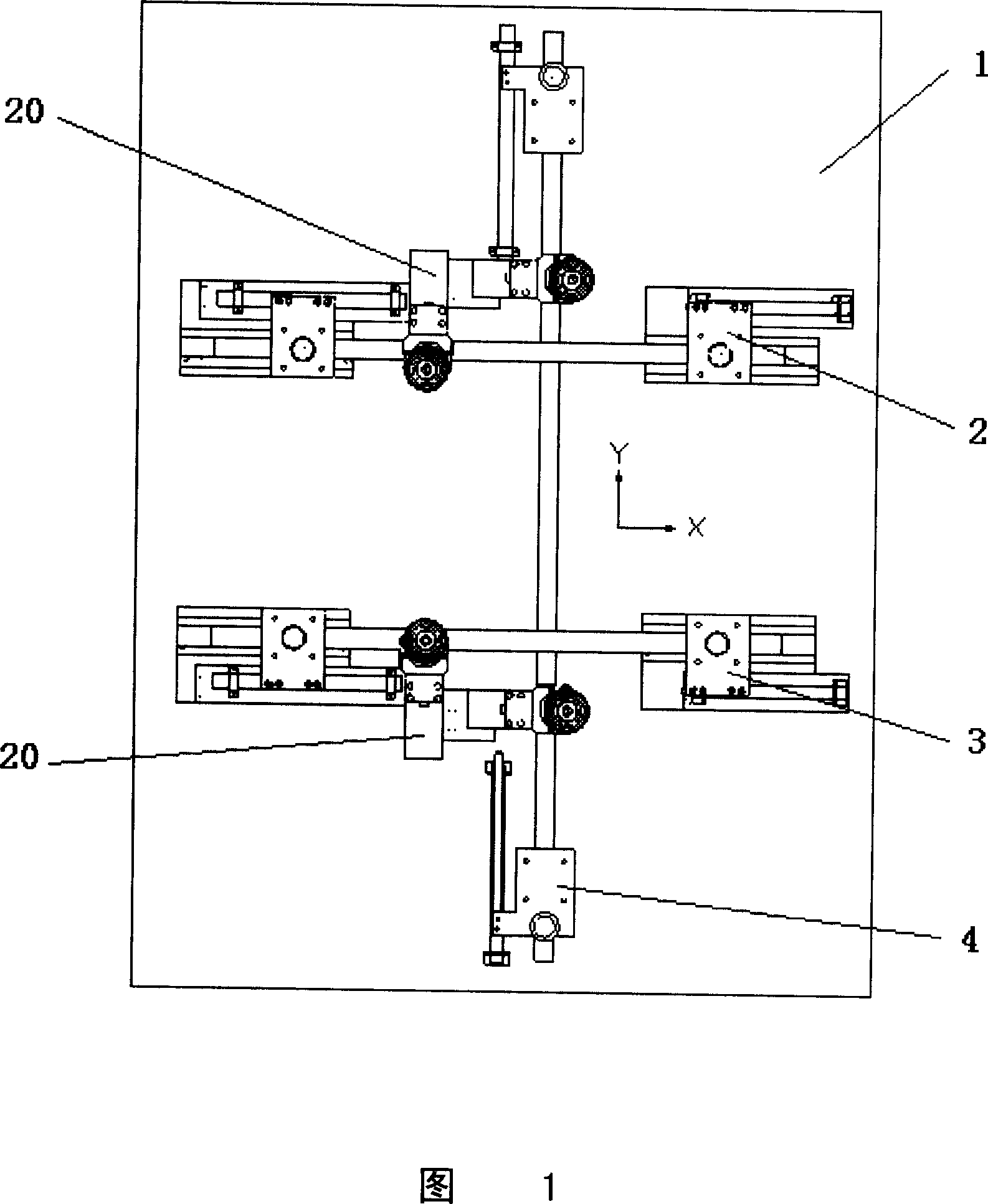
[0015] As shown in Fig. 1, the present invention comprises a centering platform 1, on the centering platform 1, two groups of centering units 2, 3 in the X direction are horizontally arranged at a certain distance, and the centering units 2, 3 in the two groups of X directions A group of centering units 4 in the Y direction are arranged horizontally in the vertical direction of 3 . Two sets of suction cup units 20 for positioning the glass in the Z direction are also arranged on the centering platform 1 .

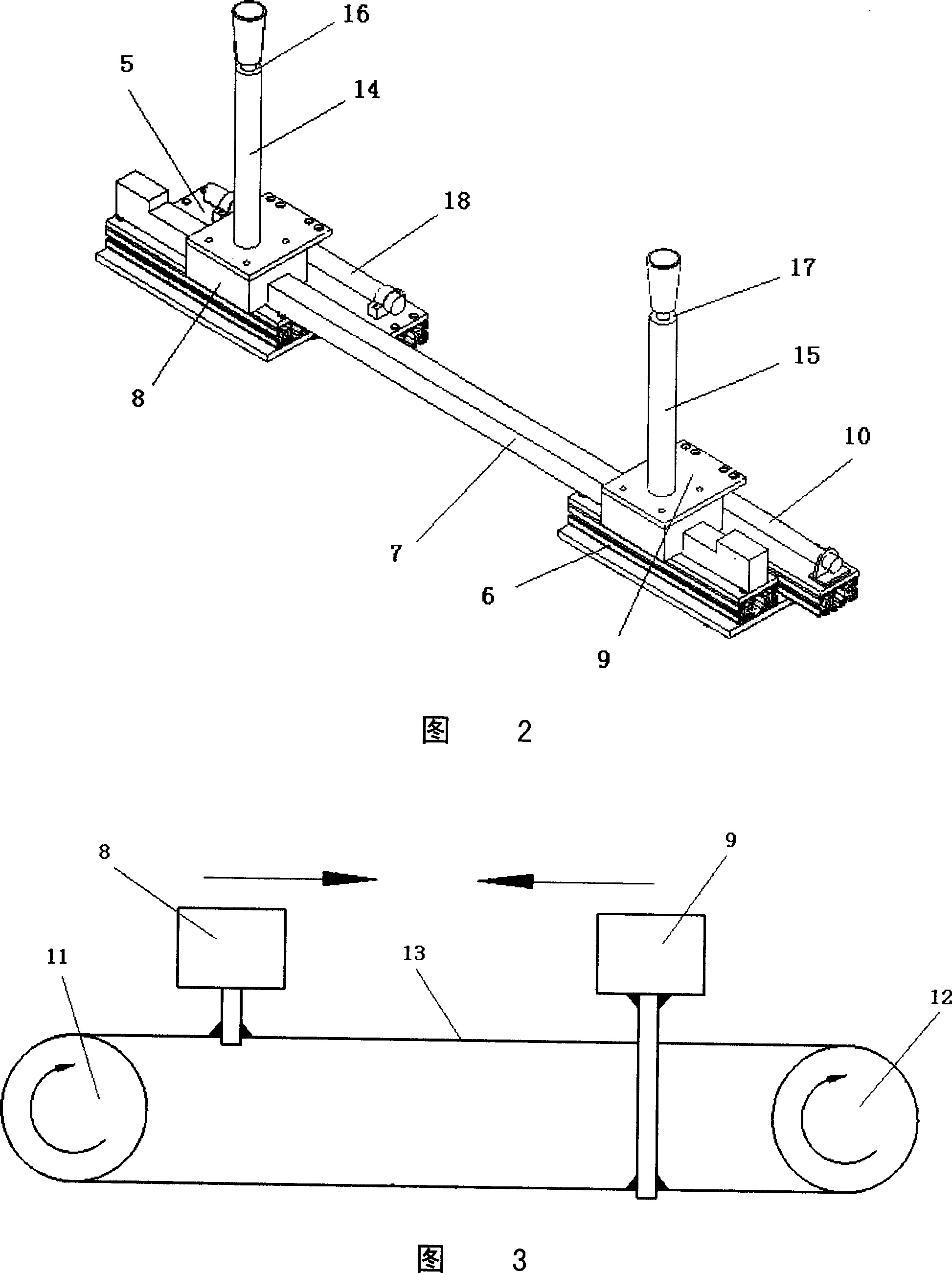
[0016] As shown in Fig. 2 and Fig. 3, the structures of the centering units 2 and 3 of two groups of X directions and the centering units 4 of one group of Y directions of the present invention are basically the same, so only one of the centering units (regardless of is that group) as an example. The centering unit includes two bases 5 and 6 whic...


PUM


Abstract

The invention relates to a rubberizing-positioning system which is worked by robots, it includes a pair of middle- stages, two groups of X directions to the unit, a group of Y direction to the unit and two groups of sucker units, the characteristic of it is that: Each group to the unit has two foundations, a chute which has two slides on it; a slide connects with an air cylinder, and another with a linear displacement sensor relatively, the head of the two slides has a pair of sticks, and joining a connection ambulacrum relatively, each group of sucker units includes two moldings, the long molding fixes together to the stage, and the short molding installs on the long molding. At the head of the two moldings establishments a adjustment board which extends to X direction and the Y direction, the adjustment board nose connects a sucker module separately; each sucker module has a sucker junction panel, a U support whose two extending terminal through a knuckle bearing pin connects at both sides of the sucker bracket, the base of the sucker bracket connects an air cylinder which brings along the sucker. The invention can carry on the pinpointing orientation to the glass in X, Y and Z directions, and distinguishes the glass model, and enable robots to control the gelatinizing procedure automatically.

Description

technical field [0001] The invention relates to a positioning system, in particular to a robot gluing positioning system for gluing automobile windshield glass. Background technique [0002] The front and rear windshields of the prior art are generally sealed with rubber strips. Because the integrity of this sealing method is not good, the noise is high, and the rubber strips are easy to age and fall off. It is directly pasted in the frame of the car, so that the glass and the body are connected as a whole, so that there is no noise, and there is no problem of aging of the sealing device. However, this new method of installing the windshield has the problem that the gluing robot is cumbersome to apply glue to the windshield. Since the front and rear windshields are all curved surfaces, when positioning, the glass can only be positioned in the X and Y directions. The precise positioning in the Z direction cannot provide precise positioning in the Z direction, so it will caus...

Claims


Application Information

Patent Timeline
Patent Type & Authority Applications(China)
IPC IPC(8): B05C5/02B05C11/02B05C11/10B05B15/06B05D7/24
Inventor 刘晏李天伟
Owner 廊坊智通机器人系统有限公司
Why Eureka
Try Eureka