Opposite infrared rays detector

A technology of infrared radiation and detectors, applied in the direction of optical device exploration, etc., can solve the problems of increasing the difficulty of installation work, inconvenient installation, impact of walls, etc., and achieve the requirements of reducing the difficulty of installation, increasing the distance, and avoiding re-rotation Effect

Inactive Publication Date: 2007-12-26
成都理想科技开发有限公司
View PDF0 Cites 2 Cited by
  • Summary
  • Abstract
  • Description
  • Claims
  • Application Information

AI Technical Summary

Problems solved by technology

[0004] 1. There is a fixed structure between the tube body and the bracket, and the angle of the tube body (with a filter plate on the tube body) cannot be adjusted. Therefore, after installation and positioning, the positions of the transmitting tube body and the receiving tube body cannot be adjusted, so that Increased the difficulty of installation work; the existing products have failed to solve the problem of wiring convenience, most products need to pull the circuit board out of the tube body when installing, insert the circuit board into the tube body after wiring, and finally install the Tube cap and bracket, very inconvenient to install
There are a small number of products that use wires to lead the terminal block out of the tube body, but the problem of rotation and fixing of the terminal block is not well solved, and the installation is still inconvenient
[0005] 2. The filter plate of existing products generally adopts circular convex lens or Fresnel lens. It is required to use a lens for each beam of infrared light. When using a multi-beam active infrared detector, the structure is more complicated
Because, if the detector is installed before the wall is painted, the surface appearance of the detector may be affected or even damaged during the painting
But after painting and then drilling and installing, it may have an impact on the wall
[0008] 5. The multi-beam active infrared detectors on the market are generally not equipped with alignment indicators that can be observed from the outside. It is difficult for installers to intuitively know whether they have adjusted to the best position when debugging.
There are also a few products with alignment indicator lights that can be observed from the outside. On the one hand, the indicator lights are not obvious, and on the other hand, they are only set on the transmitter or receiver, not both ends. It is still inconvenient for the installer to debug.

Method used


Image

  • Opposite infrared rays detector
  • Opposite infrared rays detector
  • Opposite infrared rays detector

Examples


Embodiment Construction

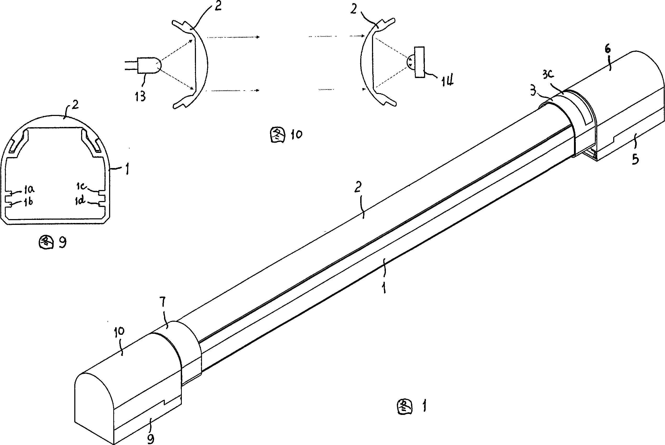
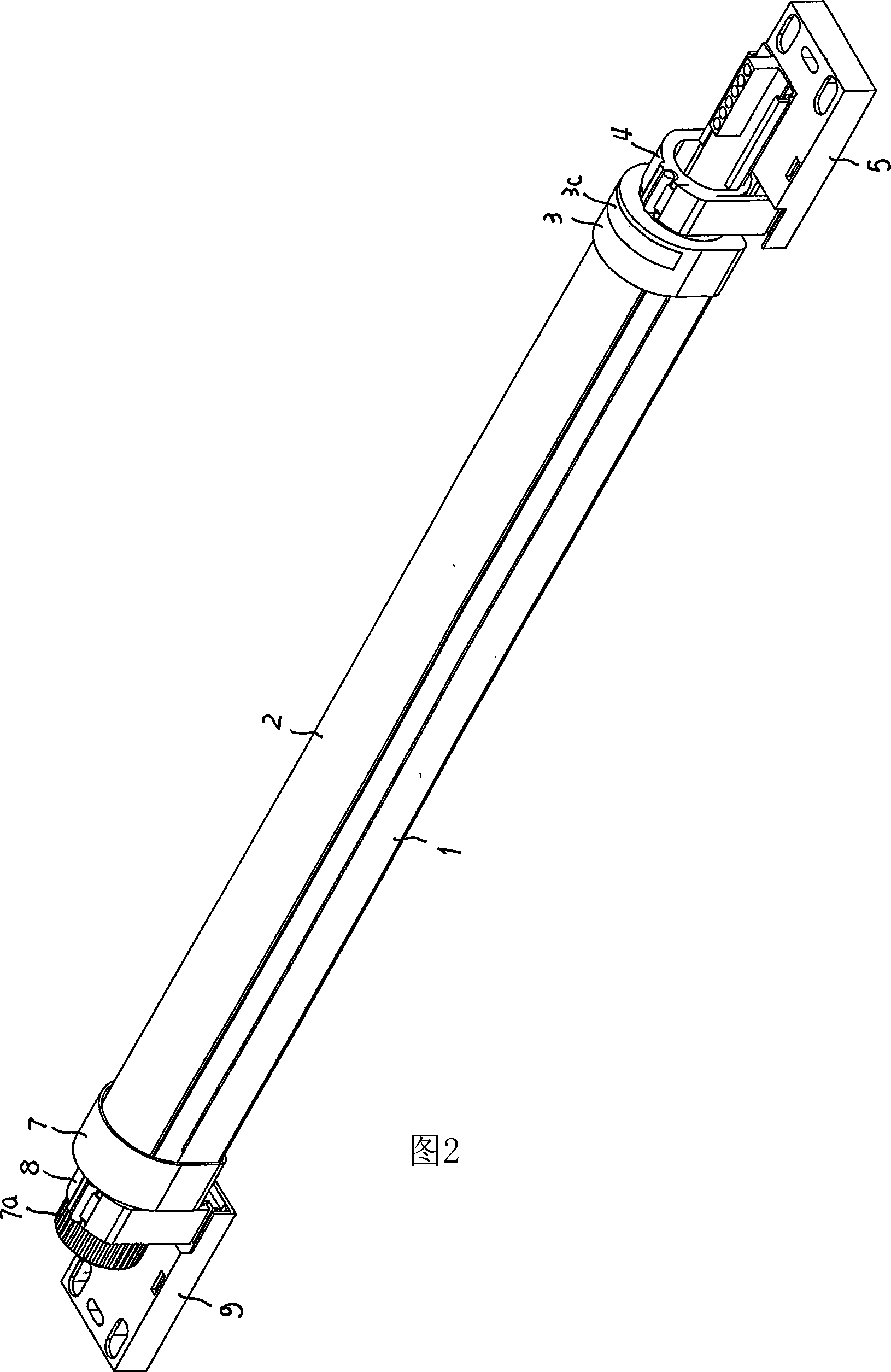
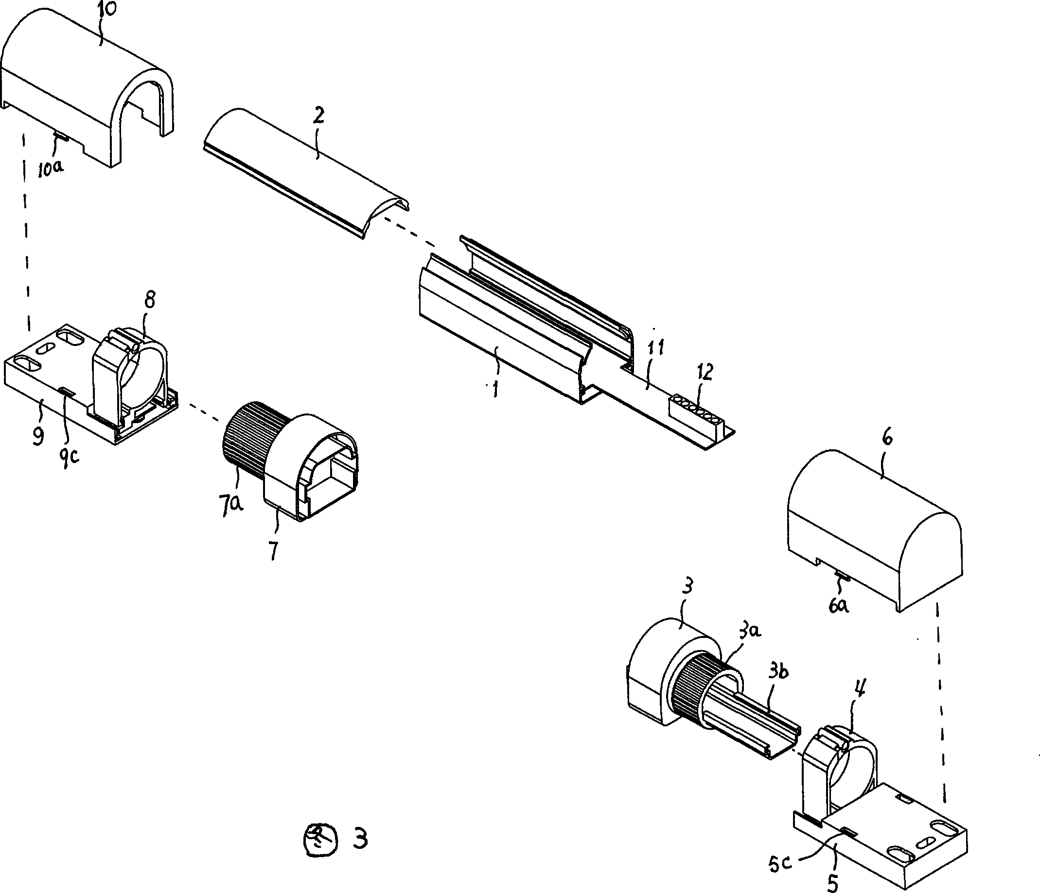
[0030] Figure 1, Figure 2 and Figure 3 show that the pipe body 1 is an aluminum alloy profile, its cross-sectional shape is composed of a rectangle and an arc shape, and its top is open, and there are symmetrical Y-shaped grooves on the left and right sides, and the left and right sides of the pipe body 1 The side inner walls are respectively provided with two longitudinal strips 1a, 1b, 1c, 1d for placing circuit boards 11 (Fig. 9). Referring to FIG. 3 , the circuit board 11 is used for installing an infrared transmitting circuit or an infrared receiving circuit, and its outer end is provided with a terminal block 12 for circuit connection. The vertical height of the inner side of the Y-shaped groove on the pipe body is higher than that of the outer side (see FIG. 9 ). The sectional shape of (infrared) filter plate 2 is made up of outwardly convex arc-shaped surface and arc-shaped tabs on the left and right sides, and the two arc-shaped tabs are matched with the Y-shaped groo...


PUM


Abstract

A correlation detector of infrared consists of circuit board set with infrared emission circuit, tube body, optical filtering board, top tube cup, bottom tube cup, base and indication lamp. It is featured as setting said tube cups on tube shaft in integral mode, inserting tube shaft set on base into support, enabling tube body to rotate for adjusting tube body to be on optimum correlation angle and enabling to stop rotating of tube body after erection.

Description

technical field [0001] The invention relates to an infrared through-beam detector, in particular to the field of manufacturing a multi-beam infrared through-beam detector for anti-theft alarms in residential areas and office areas. Background technique [0002] At present, the existing multi-beam infrared detector is mainly composed of an infrared emitting device and an infrared receiving device. The body is installed on the wall of the fortified area. The infrared rays emitted by the infrared emitting circuit are emitted through the infrared filter plate on the tube body, and then injected into the infrared filter plate of the receiver, and received by the infrared receiving head. The continuously emitted infrared rays act as an infrared electronic guardrail. role. Once someone passes by, it will block the emission and reception of infrared rays, and the alarm of the device will generate an alarm sound to warn the personnel on duty. [0003] The existing infrared through-...

Claims


Application Information

Patent Timeline
Patent Type & Authority Applications(China)
IPC IPC(8): G01V8/12
Inventor 羊贵祥高开文石皓仁
Owner 成都理想科技开发有限公司
Why Eureka
Try Eureka