Optical scanner, and mechanism for cleaning optical scanner cover glass

A light scanning device, image technology, applied in the direction of optics, optical components, instruments, etc., can solve problems such as differences in exit angles, curved scanning line traces, etc.

Inactive Publication Date: 2007-12-26
SEIKO EPSON CORP
View PDF3 Cites 7 Cited by
  • Summary
  • Abstract
  • Description
  • Claims
  • Application Information

AI Technical Summary

Problems solved by technology

[0013] In addition, when the deflecting reflective surface is twisted or curved so that the value of the surface deviation at the incident position of the beam changes with the rotation of the deflecting reflective surface, compared with when the deflecting reflective surface is composed of a pure plane, the output angle will be different. difference, which in turn produces a curvature of the scan line trajectory

Method used


Image

  • Optical scanner, and mechanism for cleaning optical scanner cover glass
  • Optical scanner, and mechanism for cleaning optical scanner cover glass
  • Optical scanner, and mechanism for cleaning optical scanner cover glass

Examples


Embodiment Construction

[0116] Hereinafter, the principle and embodiments of the optical scanning device of the present invention will be described in detail based on the drawings.

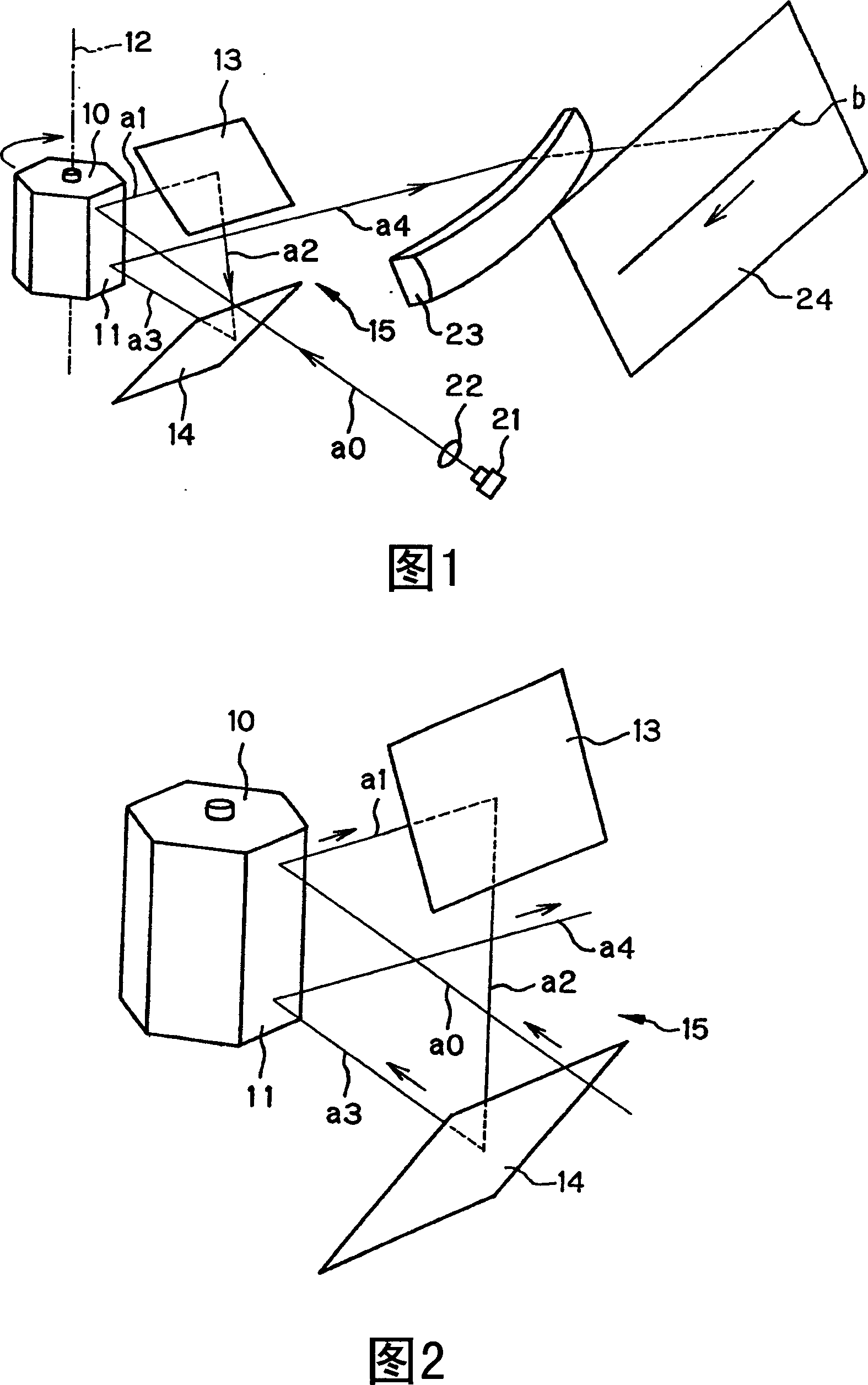
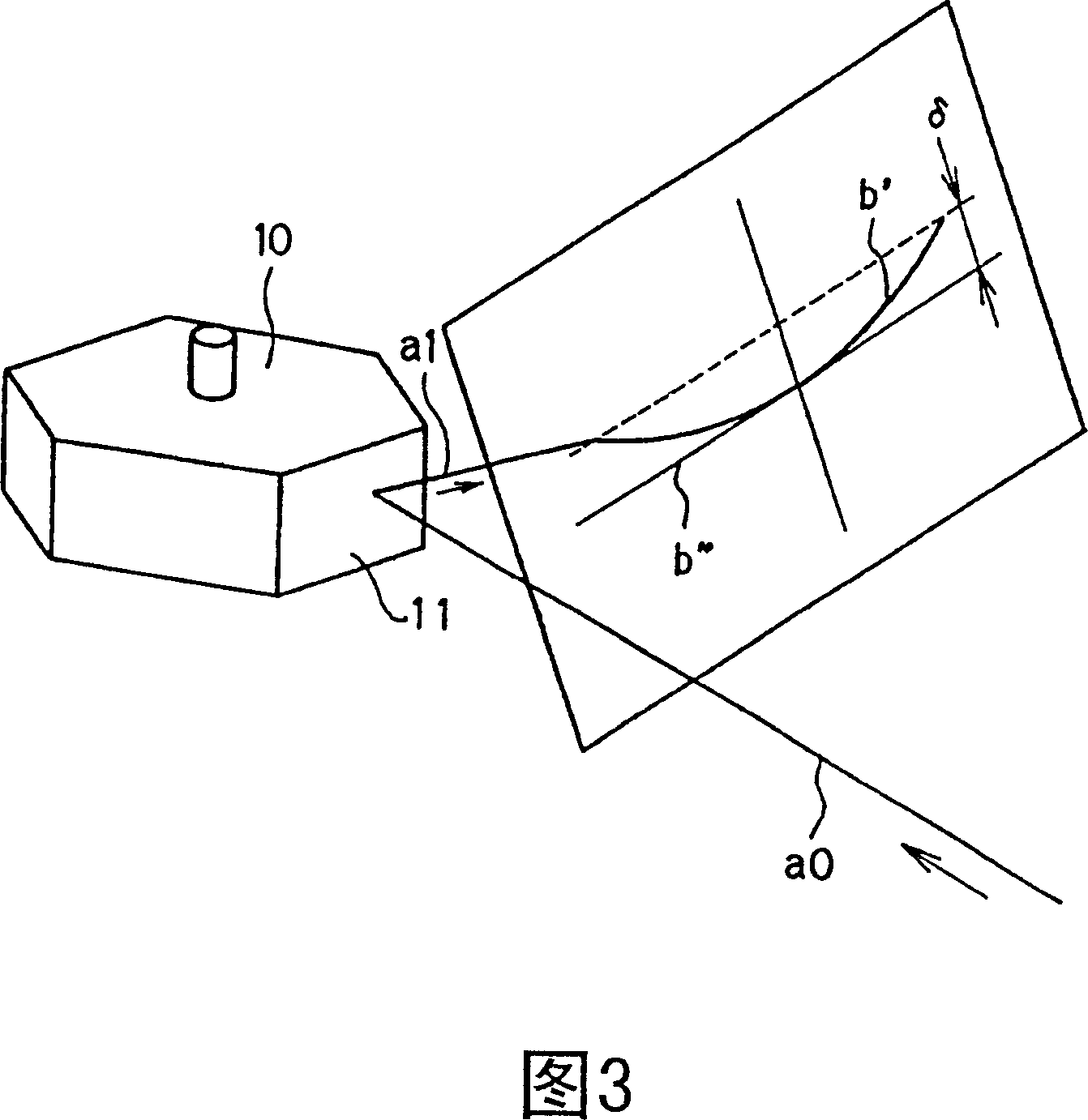
[0117] FIG. 1 is a perspective view of the overall structure of an optical scanning device according to a first embodiment of the present invention, and FIG. 2 is a perspective view of a light deflection optical system of its main part.

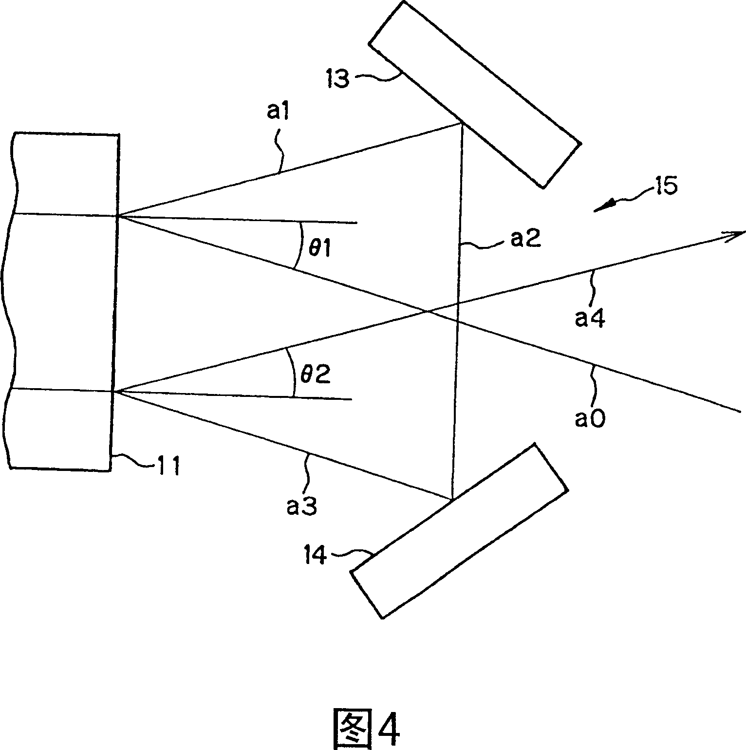
[0118] In the structure, the light deflecting portion is constituted by an optical polyhedron 10 having a plurality (six in the figure) of deflecting reflective surfaces 11 on the sides of the polyhedral column, which rotate about their rotation axes 12 . And, facing the deflection reflective surface 11 participating in the light deflection, two fixed plane mirrors 13, 14 are arranged, said fixed plane mirrors 13, 14 are at a certain angle to each other with a gap 15 between them.

[0119] Furthermore, the light from the light source 21 passes through the lens 22 into a parallel light b...


PUM


Abstract

The present invention relates to an optical scanning device in which a light beam is incident twice on a deflective reflecting facet and its object is to reduce curvature in scanning line trail or make the curvature substantially zero, or correct scanning line displacement due to the curvature in scanning line trail. Two stationary plane mirrors (13, 14) are disposed to face a deflective reflecting facet (11) which can be rotated about its rotational axis (12) such that a light beam (a1) being incident on and reflected from the deflective reflecting facet (11) is reflected by the two stationary plane mirrors (13, 14) sequentially. The reflected light beam (a3) is incident on and reflected by the deflective reflecting facet (11) again. Assuming that a plane being parallel to the rotational axis (12) and including the light beam (a0) which is first incident on the deflective reflecting facet is an incident plane, the central ray of an emergent light beam (a4) when the emergent light beam (a4) after the second reflection by the deflective reflecting facet (11) is on the incident plane and a straight line as the central ray of a light beam being projected on the incident plane when the deflective reflecting facet (11) is revolved by the maximum rotational angle are set substantially parallel to each other.

Description

[0001] This application is a divisional application of the patent application with application number 03804198.7. The filing date of the original application is May 7, 2003, and the title of the invention is "Optical Scanning Device and Cover Glass Cleaning Mechanism for Optical Scanning Device". technical field [0002] The present invention relates to an optical scanning device used for image writing and exposure in an image forming apparatus such as a laser printer, and more particularly to an optical scanning device that sequentially injects a light beam twice on a deflection reflection surface such as a rotating polygon mirror. [0003] The present invention also relates to a cover glass cleaning mechanism of an optical scanning device having a structure capable of reliably removing dust and the like adhering to the surface of the cover glass. Background technique [0004] Conventionally, Japanese Patent Application Laid-Open No. Sho 51-6563 proposes an optical scanning ...

Claims


Application Information

Patent Timeline
Patent Type & Authority Applications(China)
IPC IPC(8): G02B26/12G02B27/00
Inventor 宗和健井上望三井洋一
Owner SEIKO EPSON CORP
Why Eureka
Try Eureka