Lightning conductor

A technology of lightning protection device and electrode body, which is applied in the direction of spark gap overvoltage arrester, cable installation, lighting conductor installation, etc. It can solve the problem of high grounding cost of lightning protection device and achieve the effect of avoiding lightning

Inactive Publication Date: 2008-01-02
SANKOSHA CORP
View PDF1 Cites 1 Cited by
  • Summary
  • Abstract
  • Description
  • Claims
  • Application Information

AI Technical Summary

Problems solved by technology

Therefore, it is necessary to make the grounding resistance of the earth low, so there is a problem that the grounding cost of the lightning protection device becomes high.

Method used


Image

  • Lightning conductor
  • Lightning conductor
  • Lightning conductor

Examples


Embodiment Construction

[0020] Examples of the present invention will be described below, but are not limited to any of the examples unless the gist of the present invention is exceeded.

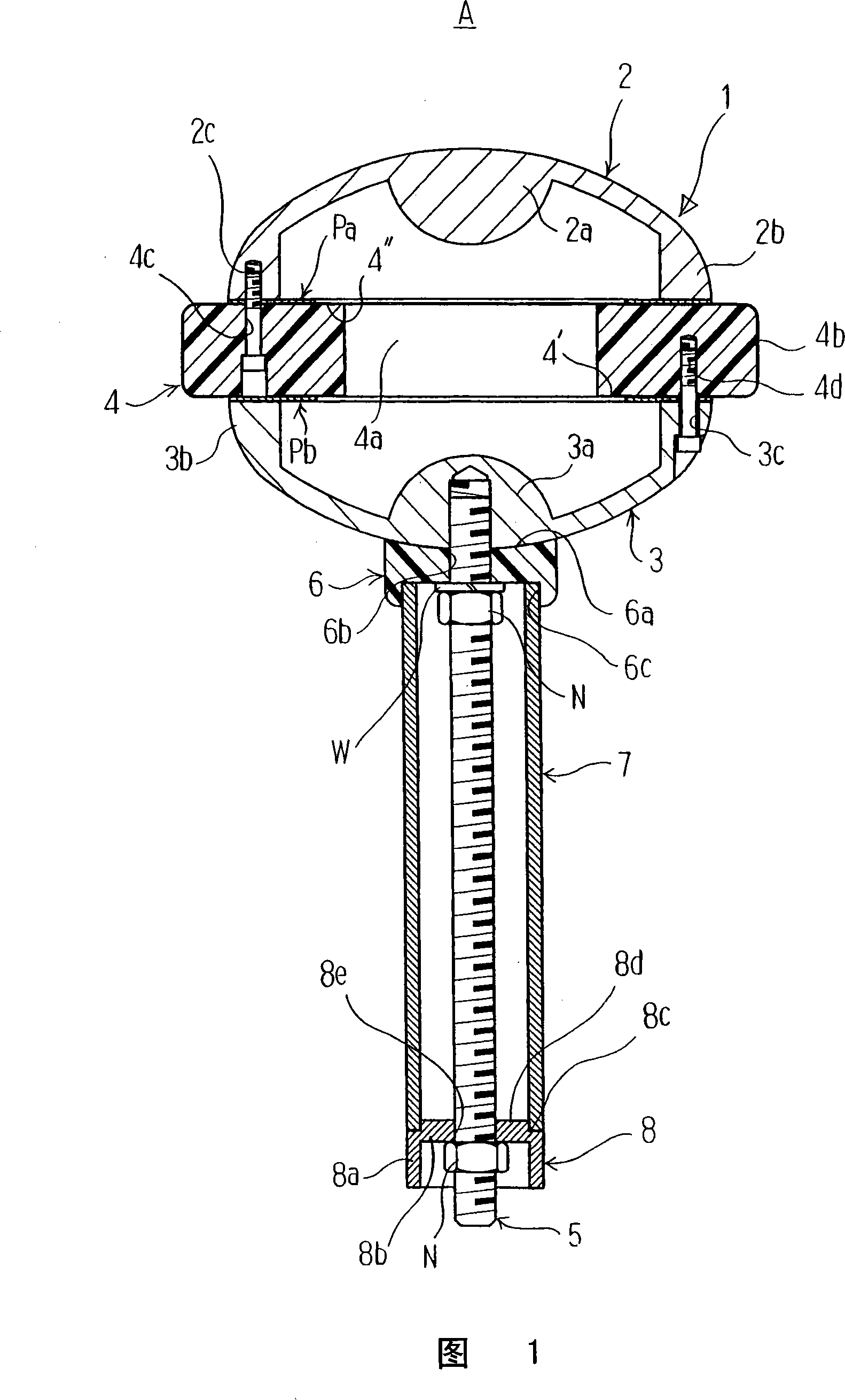
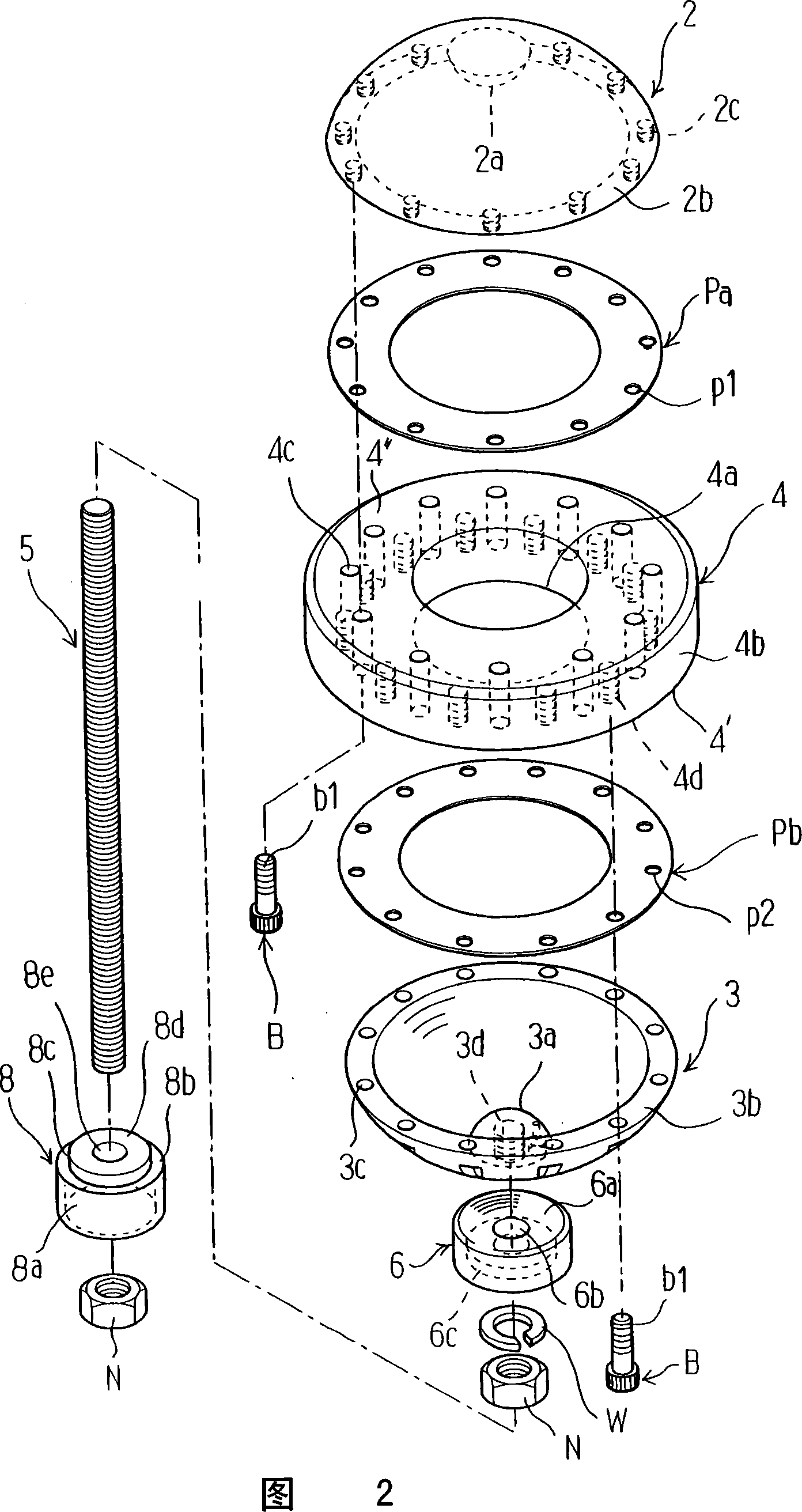
[0021] 1 is a lightning rod member, and the lightning rod member 1 is composed of an upper electrode body 2 , a lower electrode body 3 and an annular insulator 4 . The upper electrode body 2 and the lower electrode body 3 are made of metal and have at least a hollow portion. In this embodiment, the upper electrode body 2 and the lower electrode body 3 are formed as hollow bowl-shaped bodies. In addition, a hemispherical upper convex portion 2 a is formed at the top center of the upper electrode body 2 , and a hemispherical lower convex portion 3 a is formed at the bottom center of the lower electrode body 3 .

[0022] The peripheral end portion 2b of the upper electrode body 2 is formed thicker than other parts, and a plurality of threaded holes 2c are formed at predetermined intervals along the circumferential dir...


PUM


Abstract

The invention relates to a lightning arrester, comprising an hollow upper electrode, a hollow lower electrode connected to earth, ring-shaped isolator positioned between the upper and lower electrode. The lower electrode has the charges contrary to the charges distributed in the thundercloud when the thundercloud is close to the lightning electrode part. The upper electrode collects the charges contrary to the lower electrode from the peripheral atmosphere when the lower electrode removes the potential difference with the lower electrode. Therefore, the invention can prevent the charge saturation so as to avoid the thunder.

Description

technical field [0001] The present invention relates to a lightning protection device for protecting equipment and equipment from lightning damage, and in particular to a lightning protection device for preventing lightning falling around equipment and equipment. Background technique [0002] If a thundercloud is generated and expanded in the atmosphere, a leader discharge (leader lightning) occurs from the cloud base of the thundercloud toward the ground, and if the leader discharge develops, a streamer ( streamer) discharge rises. Furthermore, when the pilot discharge is combined with the streamer discharge, a discharge path is formed between the ground and the thundercloud, and a large current flows between the thundercloud and the ground through the discharge path. This phenomenon is a lightning phenomenon. [0003] Conventional lightning protection devices are configured to receive lightning through lightning prongs arranged at a position higher than protected objects...

Claims


Application Information

Patent Timeline
Patent Type & Authority Applications(China)
IPC IPC(8): H02G13/00
CPCH01C7/12H01T4/02
Inventor A·R·蒙蒂A·C·卡纳石崎诚
Owner SANKOSHA CORP
Why Eureka
Try Eureka