Disc brake and spacer element

A technology of disc brakes and isolation components, which is applied in the direction of brake components, brake types, mechanical equipment, etc., can solve the problems of excessive wear, slipping, and insufficient hardness of brake pads, and achieve reliable buffering effects

Inactive Publication Date: 2008-01-09
HALDEX BRAKE PROD AB
View PDF4 Cites 8 Cited by
  • Summary
  • Abstract
  • Description
  • Claims
  • Application Information

AI Technical Summary

Problems solved by technology

After braking, without proper separation between the brake disc and the brake pads, excessive wear and slippage of the brake pads may occur, that is, although in the released state, one or more brake discs are still in contact with the brake pads. Brake pads stay in contact
[0007] Moreover, in some cases, such a spring element has the disadvantage that it limits the free axial movement of the brake disc to a certain extent, leading to undesired slippage in the disengaged position of the disc brake
[0014] The parts corresponding to the brake disc stabilizing elements in the prior art are either not hard enough to resist the inertial force of the brake disc when driving on uneven roads; ), without placing between the splines of the brake disc and the splines of the hub a rigid part or part equivalent to a brake disc stabilizing element, in place of the sides of said splines receiving the impact

Method used


Image

  • Disc brake and spacer element
  • Disc brake and spacer element
  • Disc brake and spacer element

Examples


Embodiment Construction

[0064] In this document, the terms "axial", "radial", "rotational" and similar expressions are relative to the axle (not shown) to which the brake is connected, and received on the axle directly or through an intermediate member For brake discs, hubs or bushings, etc.

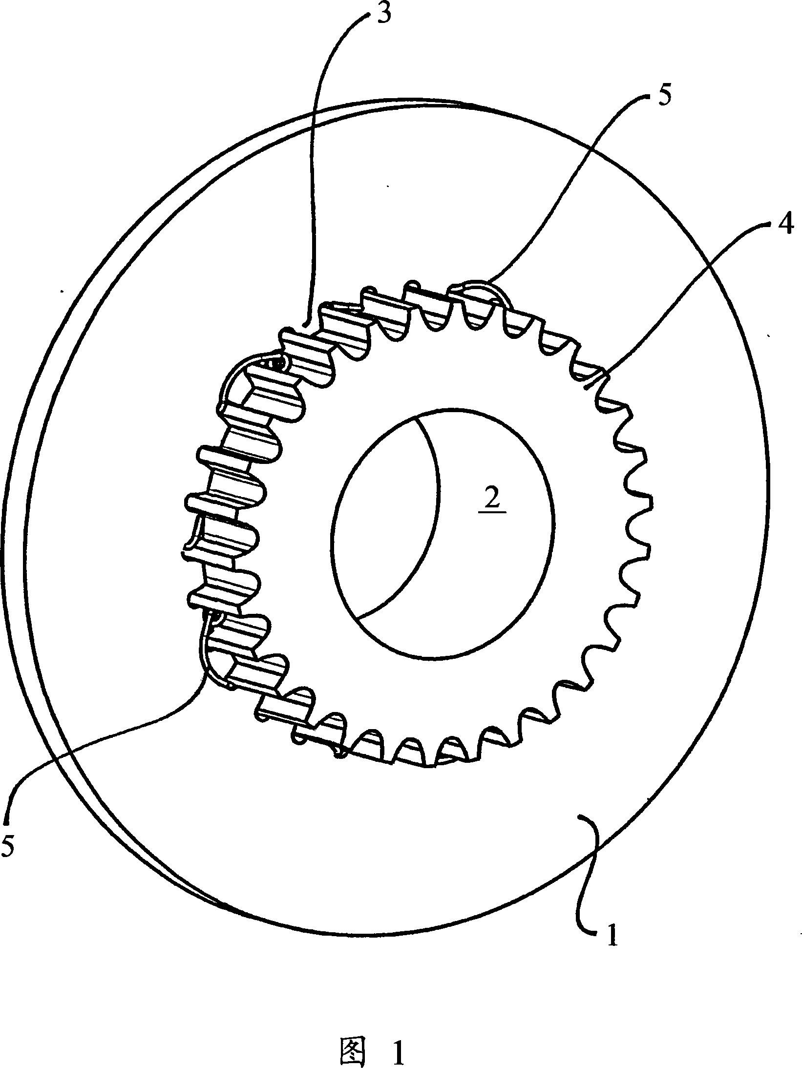
[0065] FIG. 1 schematically shows a brake disk 1 and a hub 2 , wherein the brake disk 1 is guided slidingly on the hub 2 . This arrangement can be used for any type of disc brake assembly in which at least one brake disc is slidingly guided.

[0066] The brake disc 1 comprises radially inward teeth or splines 3 which intermesh with radially outward teeth or splines 4 provided on the hub 2 . The splined engagement allows the transmission of rotational forces or torques when the brake disc 1 and brake pads (not shown) are mated and at the same time the brake disc 1 slides axially on the hub 2 .

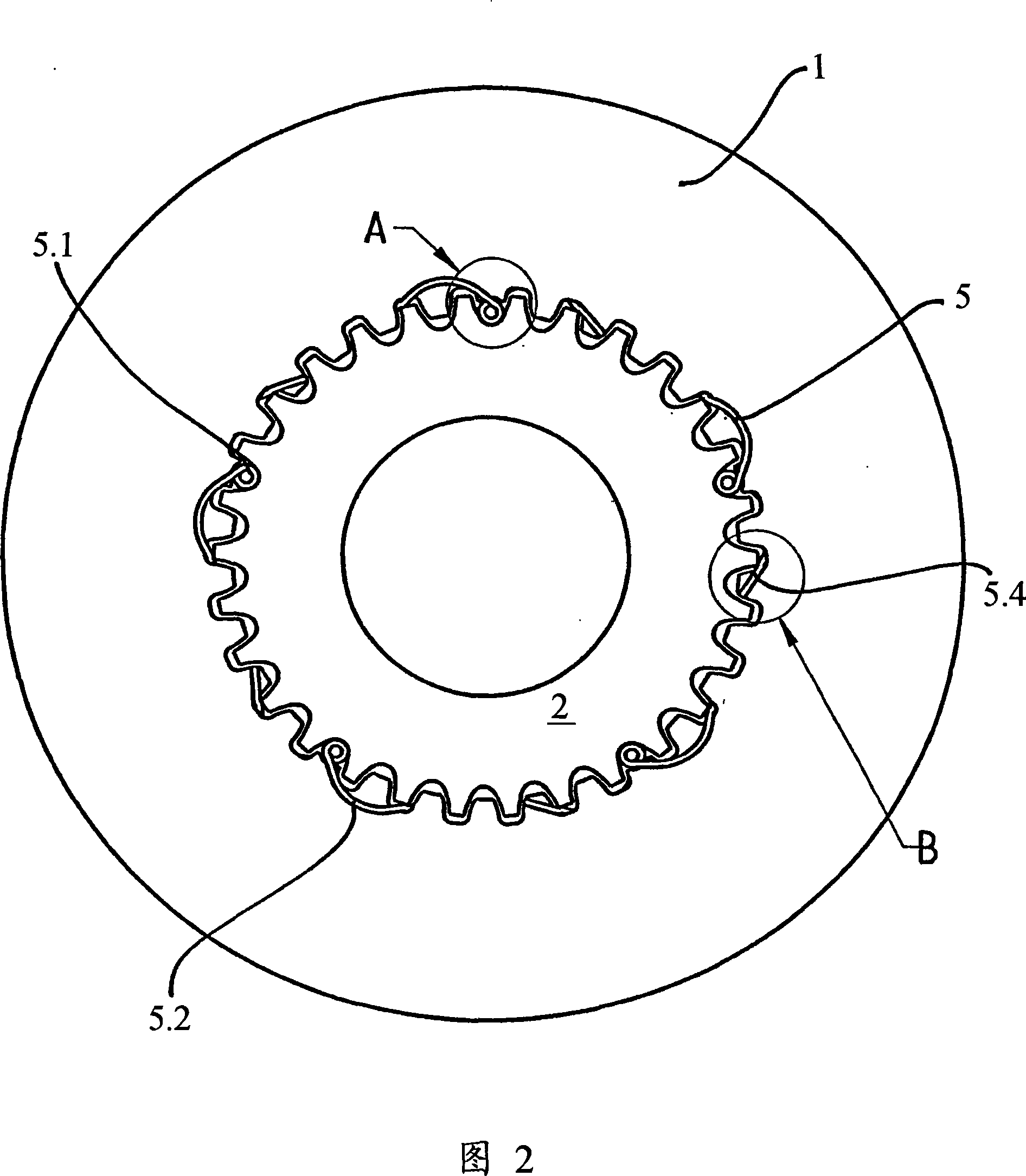
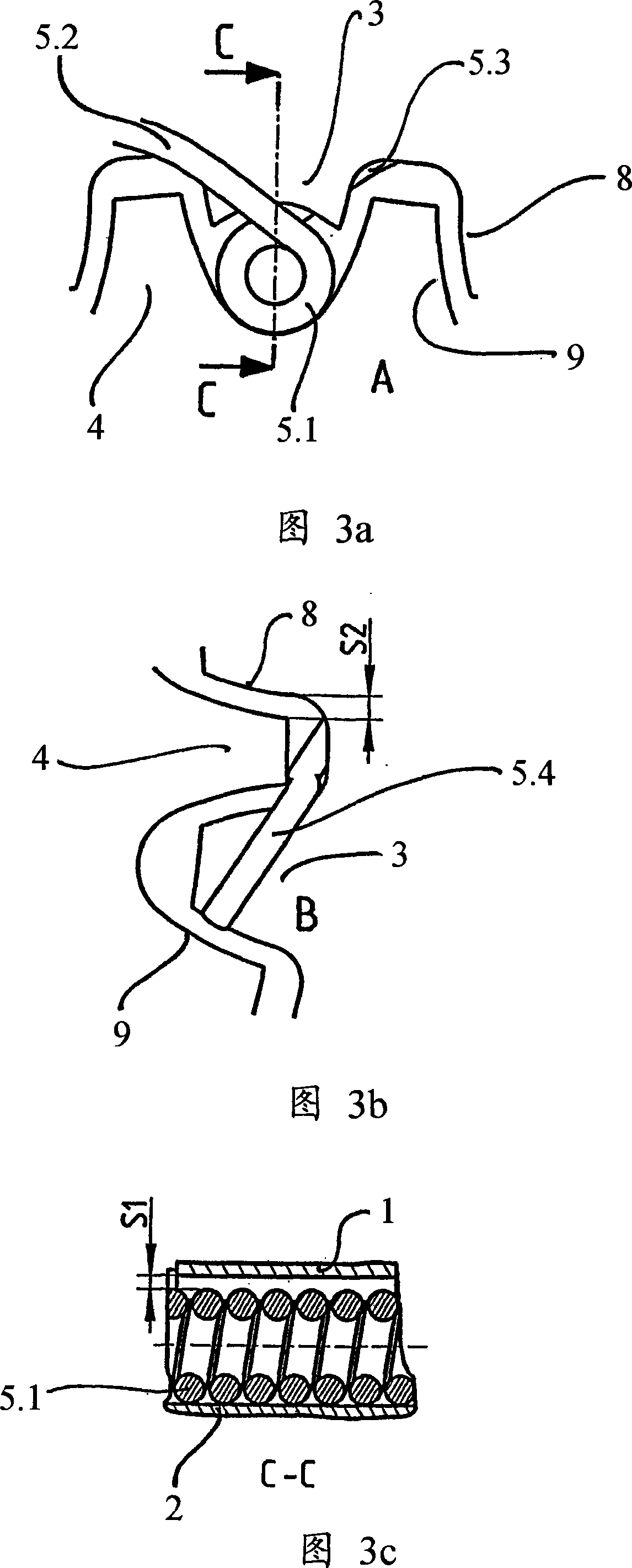
[0067] Between the splines 3 of the brake disc 1 and the splines 4 of the hub 2 , spacer elements 5 are arranged equ...


PUM


Abstract

The invention refers to a disc brake having a caliper encircling one or more brake discs, of which at least one brake disc is received slideably on a hub by means of intermeshing splines of both the brake disc and the hub, wherein spacer elements are placed between the brake disc and the hub which are arranged and configured so that contact between the flanks of the splines of the brake disc and the flanks of the splines of the hub is prevented exclusively for any radial movement of the brake disc relative to the hub.

Description

technical field [0001] The invention relates to disc brakes and spacer elements for such disc brakes. Typically disc brakes have fixed or sliding calipers. The invention relates to disc brakes with fixed or sliding calipers and one or more discs, at least one of which is sliding. The invention relates both to brakes in which the brake pads act only on a limited portion of the entire circumference, and to disc brakes in which the brake pads act along almost the entire circumference of the brake disc. The former brake is also called a spot-type disc brake. Background technique [0002] A sliding brake disc is received on a bushing, hub or similar structure, usually by means of teeth, splines, etc., or by any other means that provides both a fixed connection in the rotational direction and a sliding connection in the axial direction. A sliding brake disc is received on a hub or similar structure. The hub and bushing are received on and connected to the axle. Depending on t...

Claims


Application Information

Patent Timeline
Patent Type & Authority Applications(China)
IPC IPC(8): F16D65/092
CPCF16D65/123F16D65/128F16D2065/1376F16D2065/1384F16D2065/1364F16D2065/1392
Inventor 约兰·斯滕松约阿基姆·格里伯马克
Owner HALDEX BRAKE PROD AB
Why Eureka
Try Eureka