Piezoelectric type electroacoustical transformer

An electro-acoustic transducer, piezoelectric technology, applied in piezoelectric/electrostrictive transducers, microphone ports/microphone accessories, sensors, etc., can solve problems such as inability to bond and deviation of sound characteristics

Inactive Publication Date: 2008-01-09
TAIYO YUDEN KK
View PDF1 Cites 24 Cited by
  • Summary
  • Abstract
  • Description
  • Claims
  • Application Information

AI Technical Summary

Problems solved by technology

[0006] As shown in the above-mentioned background art, the piezoelectric vibrating plate 5 on which the piezoelectric element 7 is attached is bonded and bonded so that the vicinity of the edge portion of the piezoelectric vibrating plate 5 overlaps the annular step portion 4e of the case 4b. In the piezoelectric electroacoustic transducer supported on the above-mentioned casing 4b as a support body, the above-mentioned lead wire 9 connected to the above-mentioned other electrode of the piezoelectric element 7 of the piezoelectric vibrating plate 5 is transmitted from the above-mentioned piezoelectric vibrating plate The protruding state of the surface of the above-mentioned casing 4b leads to the outside of the above-mentioned case 4b, so there is a problem that the above-mentioned piezoelectric vibrating plate 5 cannot be connected with the above-mentioned casing 4b and the edge portion of the above-mentioned piezoelectric vibrating plate 5 along the entire circumference. The ring-shaped step portion 4e of 4b is evenly bonded, so that variations in acoustic characteristics are likely to occur

Method used


Image

  • Piezoelectric type electroacoustical transformer
  • Piezoelectric type electroacoustical transformer
  • Piezoelectric type electroacoustical transformer

Examples


Embodiment Construction

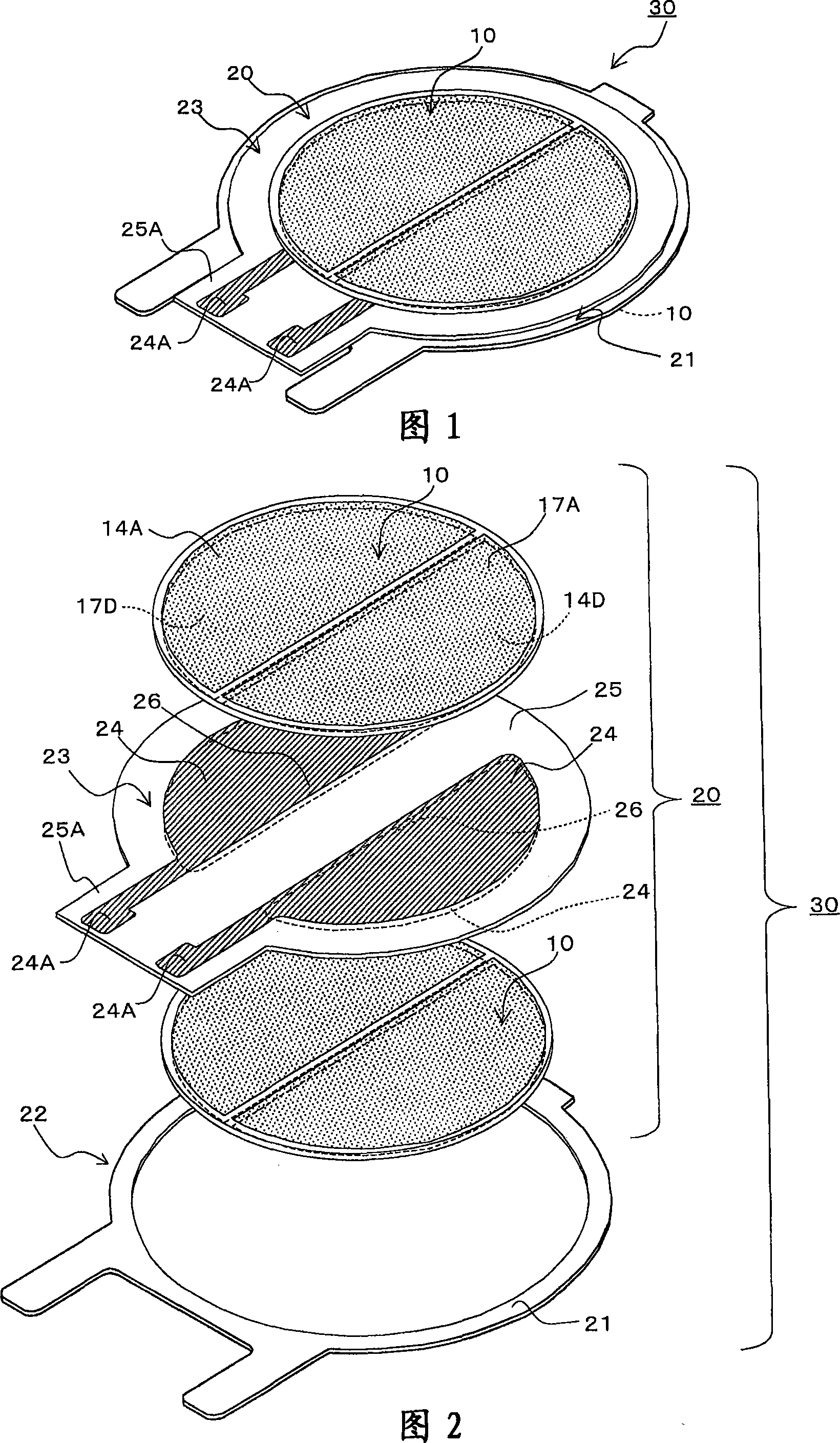
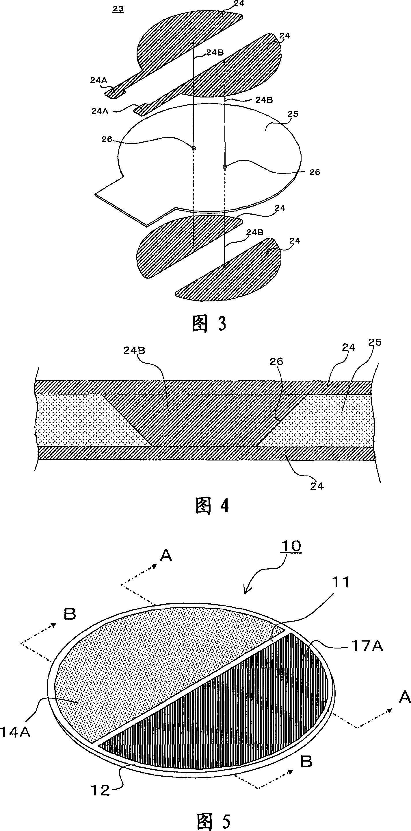
[0034] Next, a first embodiment of the piezoelectric electroacoustic transducer of the present invention will be described with reference to FIGS. 1 to 4 . FIG. 1 is an overall appearance perspective view showing a piezoelectric electroacoustic transducer 30 according to the first embodiment, and FIG. 2 is an exploded perspective view illustrating the internal structure of the piezoelectric electroacoustic transducer 30 according to the first embodiment. 3 is an exploded perspective view illustrating the internal structure of the diaphragm 23 used in the piezoelectric electroacoustic transducer 30 , and FIG. 4 is a partially enlarged cross-sectional view of the through-hole conductor 24B of the diaphragm 23 .

[0035] As shown in FIG. 1 , FIG. 2 and FIG. 3 , the piezoelectric electroacoustic transducer 30 of this embodiment has: disc-shaped first and second piezoelectric elements 10 , which are attached to the vibrating plate 23 A group of external electrodes 14 and 17 are res...


PUM


Abstract

The invention provides a piezoelectric electro-acoustic converter. The piezoelectric electro-acoustic converter has: a pair of piezoelectric elements with an outer electrode on one main surface; piezoelectric vibration plate arranging between a pair of piezoelectric elements and attaching on two main surfaces of the insulated base plate; a supporting body having the circular supporting portion along the edge portion of the piezoelectric vibration plate, in which a through hole conductor on the vibration plate is arranged in the inner area surrounded by the circular supporting portion, the connecting electrodes at two main surfaces of the vibration plate are connected mutually and a set of lead-out portion respectively connected with the electrode are formed near the edge portion of another main surface. Therefore, the invention is unnecessary to set the lead-out portion near the edge portion of the vibration plate and on the binding face of the supporting portion for connecting the electrodes, meanwhile the edge portion of the vibration plate along the whole circumference is uniformly binding to the circular supporting portion of the supporting body.

Description

technical field [0001] The present invention relates to a piezoelectric type electroacoustic transducer used as a speaker of a portable telephone, a portable information terminal, etc., and more particularly, to a piezoelectric vibration plate having a bimorph type in which the piezoelectric vibration plate A piezoelectric electroacoustic transducer with a structure in which the peripheral portion of the sensor is bonded to a support. Background technique [0002] Piezoelectric electroacoustic transducers, such as piezoelectric speakers and microphones, are widely used as simple electroacoustic transducers, and in recent years, they are especially used as speakers for mobile phones, portable information terminals, and the like. [0003] As the piezoelectric type electroacoustic transducer 1, a piezoelectric type electroacoustic transducer such as an example shown in FIG. 5 is supported on the case 4b by bonding the vicinity of the edge portion of the piezoelectric vibrating...

Claims


Application Information

Patent Timeline
Patent Type & Authority Applications(China)
IPC IPC(8): H04R17/00
CPCH04R1/08H04R17/00H04R2499/11
Inventor 德久泰一植西广明渡部嘉幸
Owner TAIYO YUDEN KK
Why Eureka
Try Eureka