Lockable and sealable connector

A connector and adjacency technology, applied in the direction of connection, parts and electrical components of the connection device, etc., can solve the problems of complexity, component processing and installation, and increased cost.

Inactive Publication Date: 2008-01-09
FISCHER CONNECTORS HLDG
View PDF3 Cites 9 Cited by
  • Summary
  • Abstract
  • Description
  • Claims
  • Application Information

AI Technical Summary

Problems solved by technology

[0012] In addition to the complexity and increased cost of this extra operation of installing the shell 3, another disadvantage is that once installed, the device cannot be dismantled unless the shell 3 is separated from the bod

Method used


Image

  • Lockable and sealable connector
  • Lockable and sealable connector
  • Lockable and sealable connector

Examples


Embodiment Construction

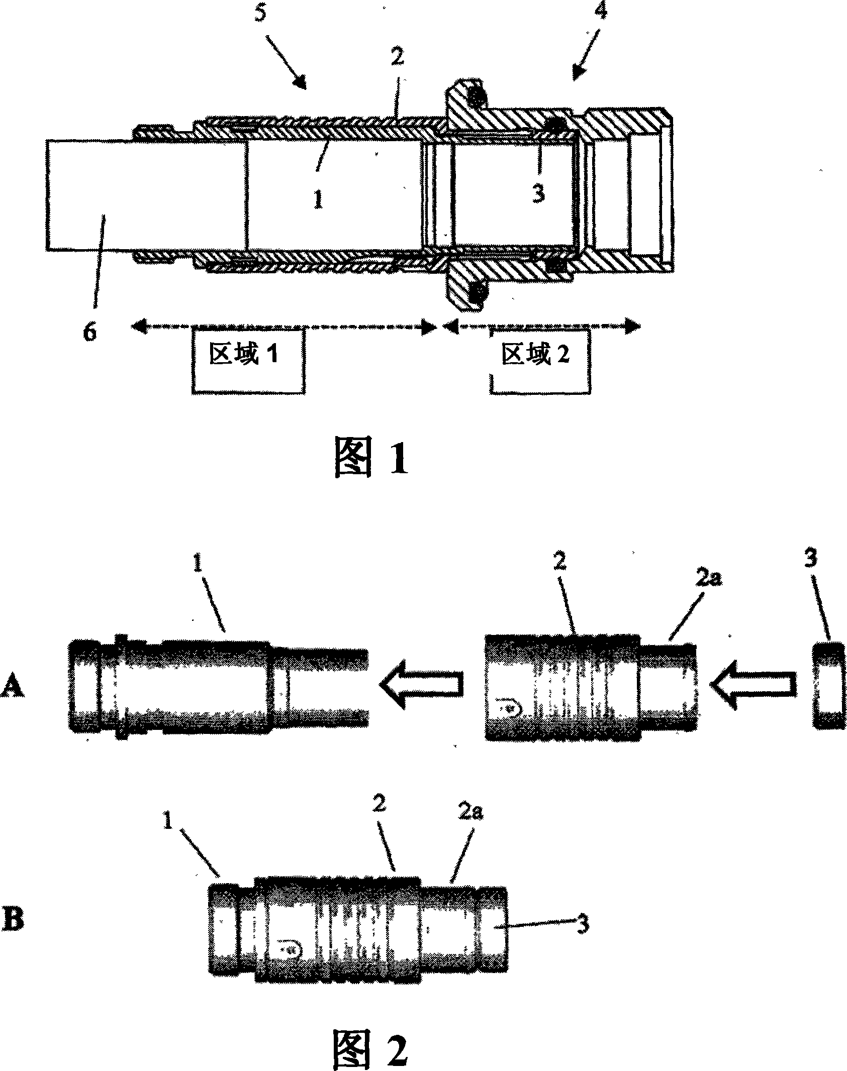
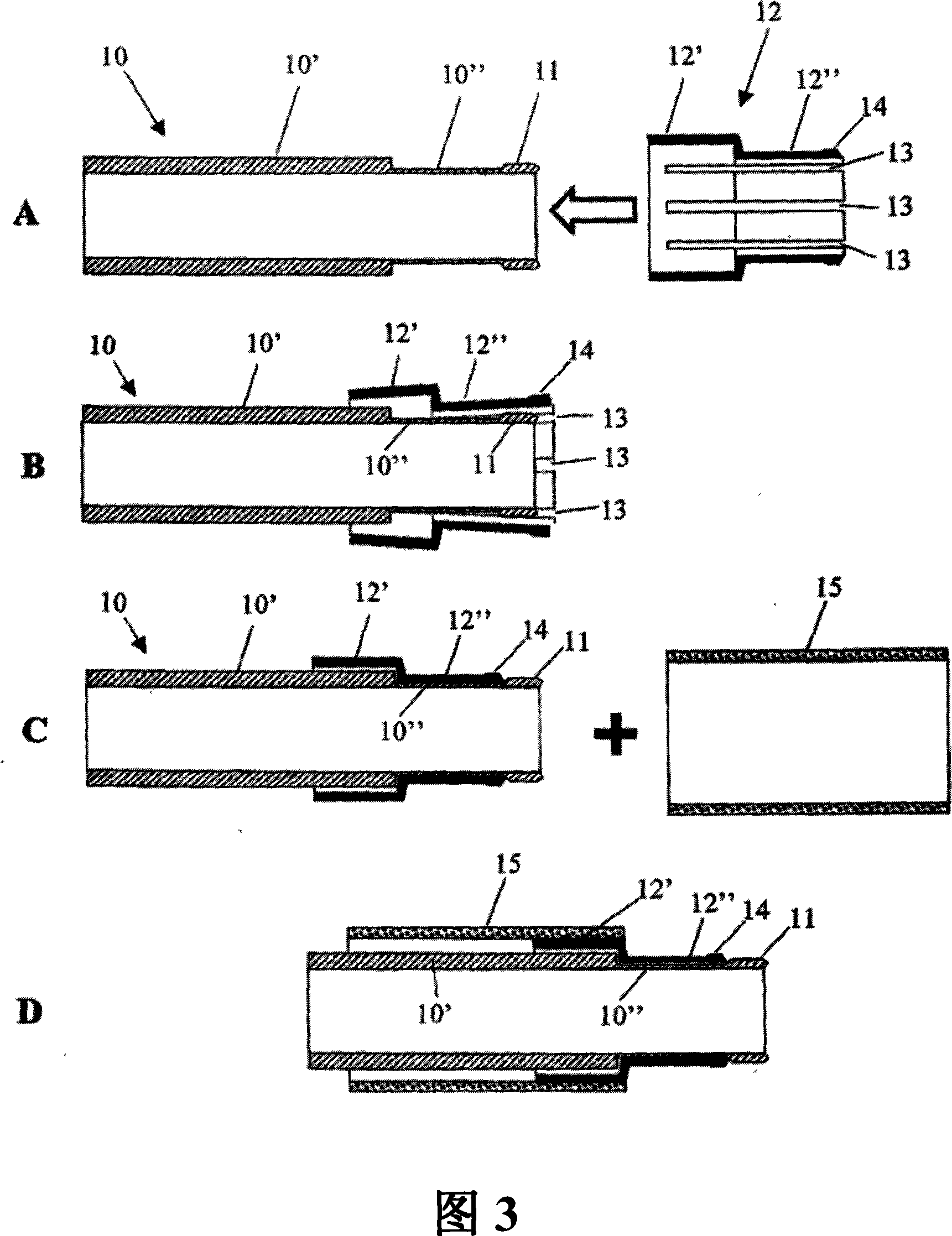
[0028] In the present invention, as shown in steps A to D in FIG. 3 , the tubular body 10 forming the plug includes a first cylindrical portion 10 ′ and a second cylindrical portion 10 ″. One end also includes a shaped portion 11 , which exactly matches the shape of the previously used shell 3 (see FIGS. 1 and 2 ). Therefore, the shell 3 is no longer needed here because it has been replaced by the shaped part of the tube body 10 .

[0029] The casing 12 includes a first part 12' and a second part 12", wherein the first part 12' is designed to surround the first part 10' of the pipe body 10, and the second part 12" is designed to surround the first part 10 of the pipe body 10 The two parts 10'', which comprise a sheet separated by a slot 13, serve the locking function as described above.

[0030] Due to the presence of the profiled portion 11, in order to install the lock sleeve 12, the lock sleeve needs to be elastic in the radial direction, which can be achieved by, for examp...


PUM


Abstract

A connector plug comprises first (10') and second (10'') cylindrical portions, wherein the second portion is arrangeable in a cylindrical cavity of a socket (6), a locking/unlocking sleeve (13) consists of first and second parts, said plug (10) and sleeve (13) comprise holding means (11, 12) which interact with each other in such a way that the rotational and/or translational displacement of the sleeve with respect to the plug portions is limited.

Description

technical field [0001] The present invention relates to "plug-and-pull" type sealed, lockable connectors. Background technique [0002] Such connectors are well known in the art, for example patent documents EP1577985, US6290525B1 and EP0875959. In the connector described in EP1577985, there is a special mechanism that locks the two parts of the connector to each other, thus preventing the connector from being unintentionally released when the cable is pulled. Accordingly, the disclosure of this document is hereby incorporated by reference into this application for reference to those components which are useful in the operation of the locking system. [0003] More particularly, this type of connector is characterized by a set of elastic plates fixedly connected to the end of a movable sleeve covering the body of one of the two connecting parts. Once the connector is connected, the elastic sheet is sealed between the part body surrounded by the elastic sheet and the exterio...

Claims


Application Information

Patent Timeline
IPC IPC(8): H01R13/627
Inventor 米歇尔·里特尔
Owner FISCHER CONNECTORS HLDG
Why Eureka
Try Eureka