
Over current protector circuit of electric backset decelerator controller

A technology of eddy current retarder and overcurrent protection circuit, which is applied in the direction of overcurrent protection, emergency protection circuit device, control electromechanical brake, etc. It can solve the problems of coil burnout, too late protection, and environmental protection, and achieve The effect of ensuring safety, improving reliability and saving the cost of use

Active Publication Date: 2008-01-16
常州明阳软件科技有限公司
View PDF0 Cites 9 Cited by
  • Summary
  • Abstract
  • Description
  • Claims
  • Application Information

AI Technical Summary

Problems solved by technology

The disadvantages of relay control are: poor reliability, frequent replacement of relays, unbalanced coil work times, easy to burn out the coil with the highest frequency of use, which brings a lot of trouble to users, and also produces a large number of relays and plastic parts. Waste not only wastes a lot of copper, steel and plastic resources in the country, but also is not environmentally friendly
Since the working current range of the high-power control module is relatively large, it may have been burned before the short-circuit current reaches its protection threshold. If a sudden short-circuit occurs, neither its own protection function nor the operation control of the MCU can protect it in time. , so that the current electronic control method is unreliable

Method used


Image

  • Over current protector circuit of electric backset decelerator controller
  • Over current protector circuit of electric backset decelerator controller
  • Over current protector circuit of electric backset decelerator controller

Examples


Embodiment Construction

[0016] The present invention will be described in further detail below in conjunction with the accompanying drawings and embodiments.

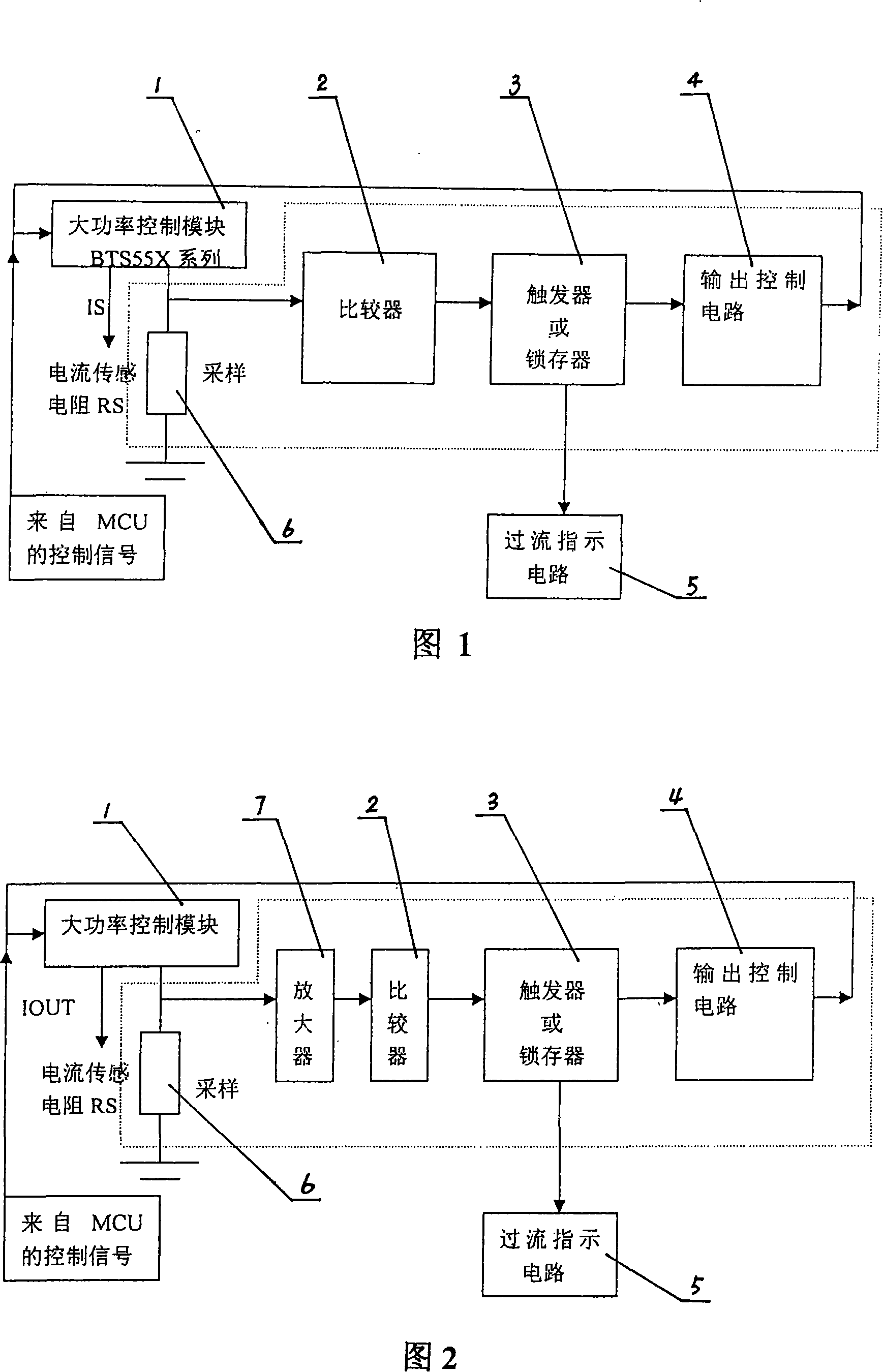
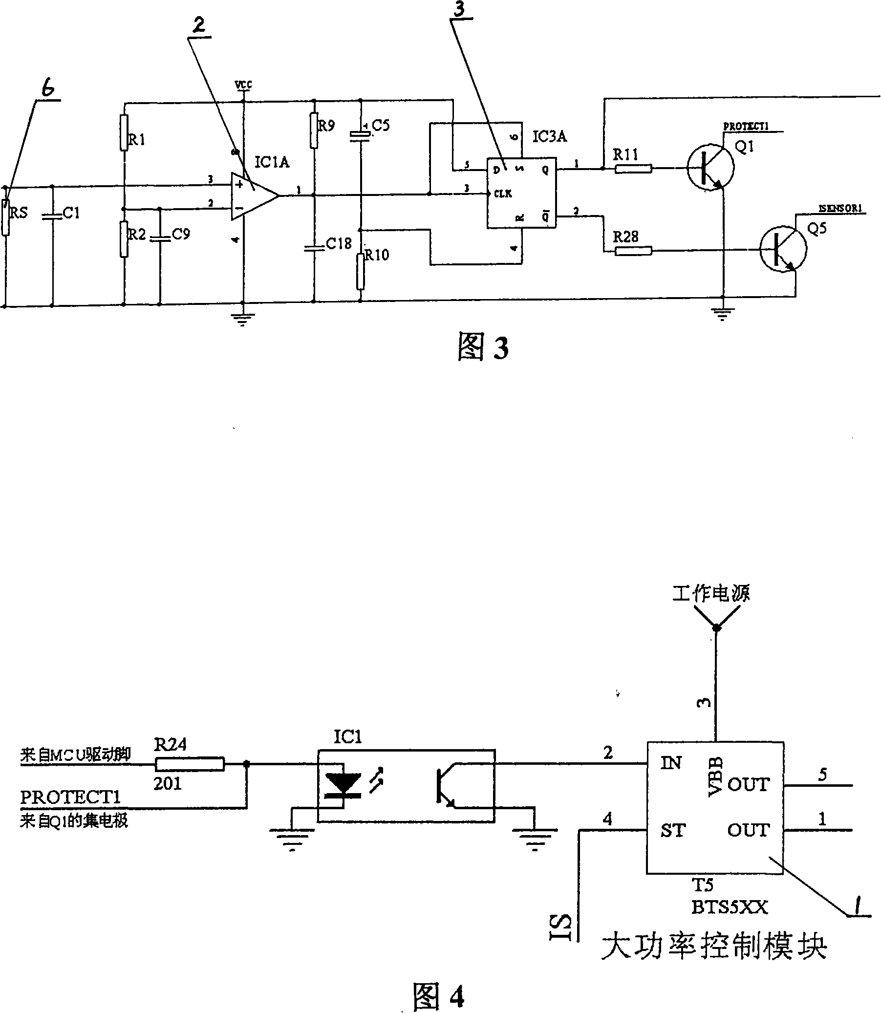
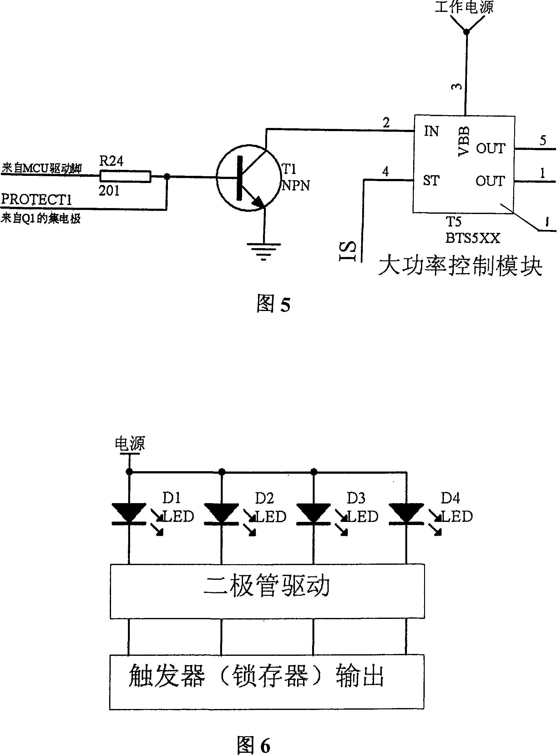
[0017] As shown in Figures 1, 3, and 6, an overcurrent protection circuit for an eddy current retarder controller includes a high-power control module 1 and an output control circuit 4, and also includes a sampling circuit 6, a comparator 2, and a trigger 3 , the comparator 2 and the sampling circuit 6 are respectively connected to the output end of the high-power control module 1, the flip-flop 3 is connected to the output end of the comparator 2, and the output end of the flip-flop 3 is connected to the output control circuit 4. The input end of the flip-flop 3 is also connected with an over-current indicating circuit 5 . The model of high power control module is BTS550 or BTS555. The sampling circuit 6 is composed of a sampling resistor RS.

[0018] As shown in Figures 1 and 6, an overcurrent protection circuit for an eddy current retarde...


PUM


Abstract

The invention relates to an over-current protection circuit of an electric vortex reducer controller, comprising a large power control module (1) and an output control circuit (4). The invention is characterized in that it also comprises a sampling circuit (6), a comparator (2) and a trigger (3); wherein, the comparator (2) and the sampling circuit (6) are separately connected with the output end of the large power control module (1); the trigger (3) is connected with the output end of the comparator (2); the output end of the trigger (3) is connected with the output control circuit (4). The invention ensures the safety of the high power control module, greatly enhances the reliability of the reducer controller, extremely lowers the use cost of user, and saves massive resources for the country such as copper material, steel, plastic, etc.

Description

technical field [0001] The invention relates to an overcurrent protection circuit of an eddy current retarder controller, which is used for the control of an auxiliary braking system of an automobile and belongs to the field of automobile electronics. Background technique [0002] Heavy-duty vehicles such as large passenger cars and trucks are prone to serious safety problems such as brake failure on long slopes. Even if they are not driving on long slopes, the expensive maintenance and replacement costs of their braking systems have always been difficult to solve. As early as the 1970s, the United States issued a law stipulating that electric eddy current retarders must be installed on passenger cars and trucks over 5 tons. In our country, due to various reasons such as the consumption ability of users, there have been no relevant laws and standards issued. However, with the improvement of economic affordability and the emphasis on safety, the installation and use of eddy c...

Claims


Application Information

Patent Timeline
IPC IPC(8): H02H7/00H02H3/08H02P15/00
Inventor 朱阳明
Owner 常州明阳软件科技有限公司
Learn More