Emergency braking device for a lift cabin

A technology of emergency braking and elevator car, which is applied in the direction of transportation and packaging, elevators, etc., and can solve the problems of insufficient safety and reliability of elevators

Active Publication Date: 2008-01-16
WITTUR
View PDF2 Cites 5 Cited by
  • Summary
  • Abstract
  • Description
  • Claims
  • Application Information

AI Technical Summary

Problems solved by technology

[0011] This solution is not safe and reliable enough for elevators
Grease is likely to get on the wheel and as a r

Method used


Image

  • Emergency braking device for a lift cabin
  • Emergency braking device for a lift cabin
  • Emergency braking device for a lift cabin

Examples


Embodiment Construction

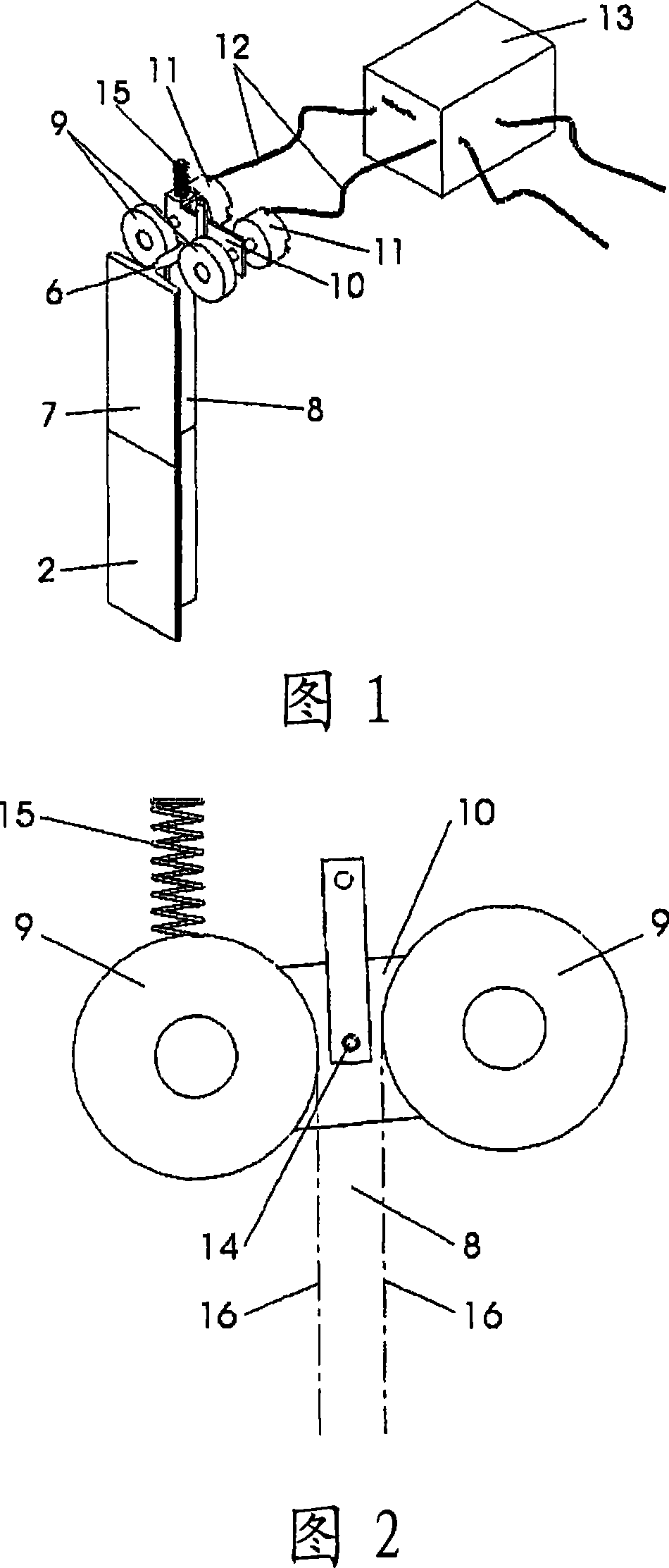
[0027] As shown in FIG. 1 , the guide rail 2 has a rail head 8 connected via a web 6 to a rail base 7 .

[0028] The wheels 9 rest against the sides of the rail head 8 , are held rotatably in a rocker 10 (see also FIG. 2 ), and are connected in a rotationally fixed manner to a sensor 11 . The sensor 11 is connected via a signal line 12 to a mechanism 13 for detecting excessive speed.

[0029] As shown in FIG. 2 , the rocker 10 is pivotably arranged about an axis 14 between two wheels 9 and is under the force of a spring 15 , which is supported on a not-shown support and serves to rotate the rocker 10 , and then the wheel 9 is pressed tightly on the two side surfaces 16 of the rail head 8 . Since the net distance between the two wheels 9 is only slightly smaller than the width of the rail head 8 and the point of application of the spring 15 is far away from the axle 14 of the fork 10, a corresponding leverage is produced, even if the spring 15 is relatively weak. High wheel 9...


PUM


Abstract

According to the invention, a lift cabin is equipped with a detector (11) that records the speed of the cabin, said detector comprising a unit (13) that identifies an excess speed and that electrically controls a braking device. The aim of the invention is to ensure the reliable detection of the speed of the lift cabin. To achieve this, in order to determine said speed, two rollers (9) are provided on a guide track (2). The speed of each roller (9) is recorded independently by detectors (11) and the unit (13) triggers an emergency braking procedure, if one of the detectors (11) indicates an excess speed. The two rollers (9) can be mounted to pivot on a rocker bar (10) on either side of the guide track (2), the rocker bar (10) being eccentrically pre-tensioned by a spring (15). The invention also relates to a method, according to which the actuating force for the braking device can be mechanically increased with the aid of the rollers.

Description

technical field [0001] The invention relates to an emergency braking device for an elevator car according to the preamble of claim 1 . Background technique [0002] The elevator is equipped with a braking device or safety gear for stopping the elevator car at impermissibly high speeds, such as occurs in the event of a control failure or rope breakage. [0003] In known arrangements of this type, a brake or safety gear is actuated by an overspeed governor fixedly installed in the hoistway or in the machine room, which will cause the overspeed governor to rotate when the elevator car is running. For this reason, be provided with a closed speed limiter rope, it walks around the speed limiter (usually at the highest position in the hoistway) at one end, and the other end walks around the tension pulley (usually at the lowest position in the hoistway). The speed-limiting rope is connected to the braking device or safety gear of the elevator car at one point, so that it is driven...

Claims


Application Information

Patent Timeline
IPC IPC(8): B66B5/06B66B5/16
CPCB66B5/06B66B5/18
Inventor 弗朗茨·约瑟夫·卡纳伯恩哈德·海德福格尔于尔根·卡纳
Owner WITTUR
Why Eureka
Try Eureka