A combined gear oil stirring experimental device and method thereof

An experimental device, combined gear technology, applied in the direction of machine gear/transmission mechanism testing, etc., can solve the problems of installation errors, no exploration, no comparative analysis of gears and wheel discs, etc., to reduce installation errors, easy installation methods, and reduced installation. effect of time

Active Publication Date: 2018-02-06
YANCHENG INST OF TECH
View PDF6 Cites 0 Cited by
  • Summary
  • Abstract
  • Description
  • Claims
  • Application Information

AI Technical Summary

Problems solved by technology

The internal factors such as the modulus of the gear and the size of the tooth surface of the gear are rarely explored, and there is no comparative analysis of the churning loss of the gear and the wheel. The replacement of the gear or the wheel during the experiment will cause installation errors, which is not conducive to oil churning. The measurement of the loss; the current research on the churning loss has not explored the influence of the distance from the gear to the inner wall on the churning loss
These factors may be the main reasons for the churning loss

Method used


Image

  • A combined gear oil stirring experimental device and method thereof
  • A combined gear oil stirring experimental device and method thereof
  • A combined gear oil stirring experimental device and method thereof

Examples


Embodiment 1

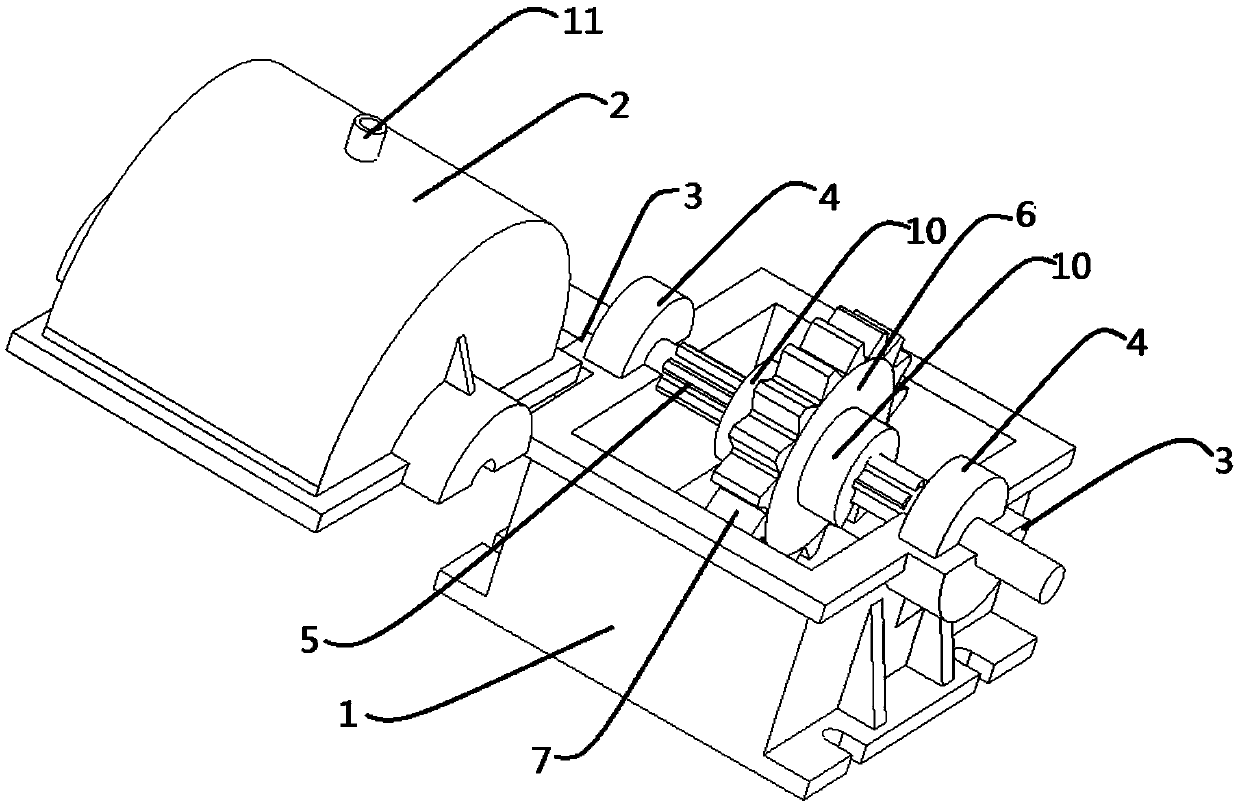
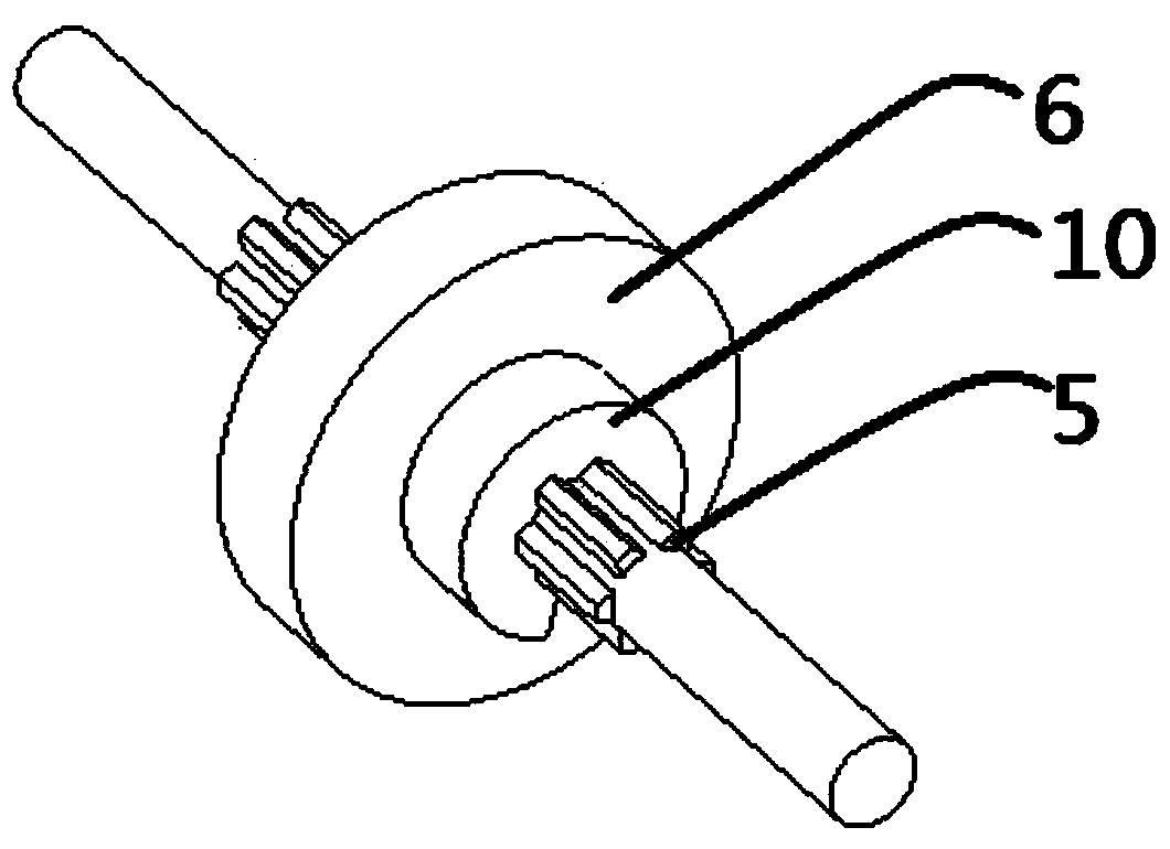
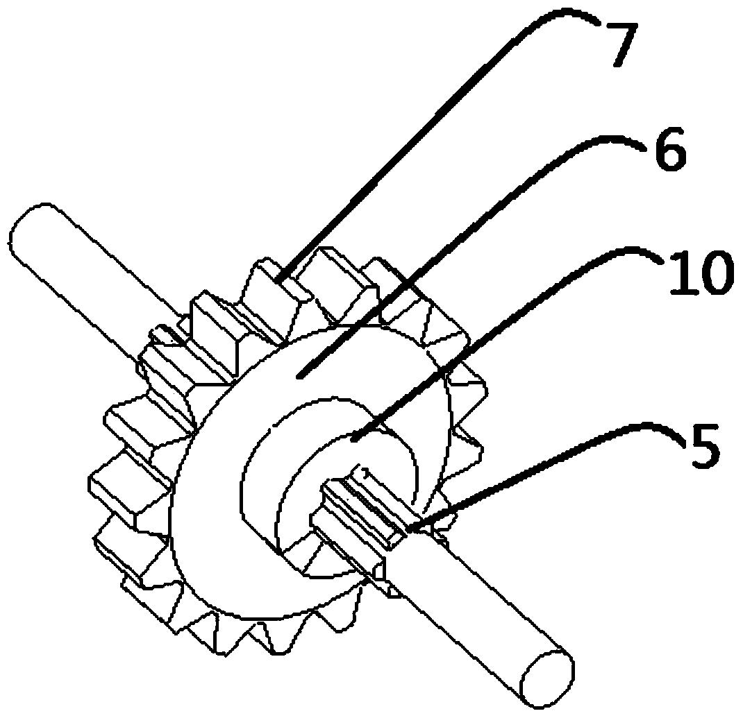
[0027] Embodiment 1: refer to Figure 1-6 As shown, a combined gear oil stirring experimental device includes a box body 1, a box cover 2 arranged on the box body 14, bearing seats 3 arranged on both sides of the box body 1, and fixed to the bearing seats by bearings 4 at both ends 3 on the spline stepped shaft 5, the spline stepped shaft 5 is set with a spline disc 6, and a spline gear assembly or a spline wheel assembly is set outside the spline disc 6; the spline gear assembly includes at least An external gear ring 7, when the number of external gear rings 7 is ≥ two, an internal gear ring 8 is set between two adjacent external gear rings 7; the spline wheel assembly includes at least one pair of external gear rings 7 and The inner gear ring 8, the outer gear ring 7 and the inner gear ring 8 are arranged at intervals from the inside to the outside; at the same time, one end of the spline stepped shaft 5 is connected to the speed torque sensor 1 and the drive motor, and the...

Embodiment 2

[0036] Embodiment 2: for different diameters, different modulus and the combined gear oil stirring experimental method of different number of teeth gears or roulette, its concrete method is as follows:

[0037] (1) One end of the splined stepped shaft 5 is connected with a rotational speed torque sensor one and a drive motor, and the other end is connected with a rotational speed torque sensor two and a dynamometer motor, and the splined disk 6 is moved to a certain position, and used Circlips 10 on both sides are axially fixed, and a plastic rack of a certain type is selected to be bent into an outer gear ring 7, which is set on the spline disc 6, and the box cover 2 is covered. If it is necessary to measure gears with different modulus and different numbers of teeth , replace different types of plastic racks to complete;

[0038] (2) Exploration of oil churning loss of gears and discs. Experimental testing is a discontinuous process. It is necessary to determine the output s...

Embodiment 3

[0040] Embodiment 3: For the combined gear churning test method of gears or wheel discs at different axial positions, its specific method is as follows:

[0041] (1) One end of the splined stepped shaft 5 is connected with the speed torque sensor one and the drive motor, and the other end is connected with the speed torque sensor two and the dynamometer motor, and the speed and torque at different axial positions on the splined stepped shaft 5 are detected. Oil churning loss, and the influence of the distance between the gear and the inner wall on the oil churning loss;

[0042] (2) This exploratory experiment test is a discontinuous process, and the axial position test points need to be set according to the length of the splined stepped shaft 5: s 1 …s i …s n , determine the range of drive motor output speed and torque according to the peak power of the drive motor, and set the speed of the drive motor to be: n 1 …n j …n m , move the splined disc 6 to the axial position ...


PUM


Abstract

The invention discloses a combined gear oil stirring experiment device, which comprises a box body, a box cover arranged on the box body, bearing seats arranged on both sides of the box body, and a spline ladder fixed on the bearing seats through bearings at both ends shaft, a splined disk is fixed on the splined stepped shaft, and a splined gear assembly or a splined wheel assembly is set outside the splined disk; the splined gear assembly includes at least one external gear ring, when the external gear ring When the number is ≥ two, an inner gear ring is fitted between two adjacent outer gear rings; the spline wheel assembly includes at least one pair of outer gear rings and inner gear rings, and the outer gear rings and inner gear rings are sequentially arranged from inside to outside Arranged at intervals; at the same time, one end of the splined stepped shaft is connected to the speed torque sensor 1 and the drive motor, and the other end of the splined stepped shaft is connected to the speed torque sensor 2 and the dynamometer motor; the advantage of the present invention is that it is easy to install and replace Gears or discs with different diameters, modulus, and number of teeth can achieve accurate axial displacement positioning.

Description

technical field [0001] The invention relates to a power loss measuring device, in particular to a combined gear oil stirring experimental device and a method thereof. Background technique [0002] The current cause of the power loss of the oil stirring mechanism is mainly the research on the external factors of the power loss of the oil stirring mechanism. The internal factors such as the modulus of the gear and the size of the tooth surface of the gear are rarely explored, and there is no comparative analysis of the churning loss of the gear and the wheel. The replacement of the gear or the wheel during the experiment will cause installation errors, which is not conducive to oil churning. The measurement of the loss; the current research on the churning loss has not explored the influence of the distance from the gear to the inner wall on the churning loss. These factors may be the main reasons for churning loss. Contents of the invention [0003] The purpose of the pre...

Claims


Application Information

Patent Timeline
Patent Type & Authority Patents(China)
IPC IPC(8): G01M13/02
Inventor 王斌张佩管文
Owner YANCHENG INST OF TECH
Why Eureka
Try Eureka