
Flexuose combined spherical hinge and producing/assembling method of the same

A zigzag, combined technology, applied to springs, springs/shock absorbers, mechanical equipment, etc. made of plastic materials, to achieve the effect of improving performance, increasing axial stiffness, and reducing the ratio of radial and axial stiffness

Active Publication Date: 2008-01-23
ZHUZHOU TIMES NEW MATERIALS TECH
View PDF0 Cites 17 Cited by
  • Summary
  • Abstract
  • Description
  • Claims
  • Application Information

AI Technical Summary

Problems solved by technology

[0002] The ball joint type rubber elastic element is a commonly used rubber-metal composite damping element, which can be widely used in various vibration damping places, especially in the bogies of rolling stock. The most common application is the three Large-scale (metal jacket + rubber + mandrel) structure, and this structure has some characteristics, but also has disadvantages. The characteristic is that their performance can basically meet the use of various working conditions. The disadvantage is that when the ball joint When the ratio of radial and axial stiffness is less than 5:1, this structure cannot meet the requirements
[0003] In recent years, with the advancement of technology, several new structures have been developed that can achieve a radial and axial stiffness ratio of less than 5:1, but these new structures are designed on the premise of a larger installation space Yes, when the effective diameter of the product is less than 100, it is difficult to design a ball joint that can achieve a 5:1 or even smaller radial and axial stiffness ratio structure while ensuring the strength and safety of the mandrel.

Method used


Image

  • Flexuose combined spherical hinge and producing/assembling method of the same
  • Flexuose combined spherical hinge and producing/assembling method of the same

Examples


Embodiment Construction

[0019] The drawings show a specific embodiment of the present invention, and the present invention will be further described below through the drawings and embodiments.

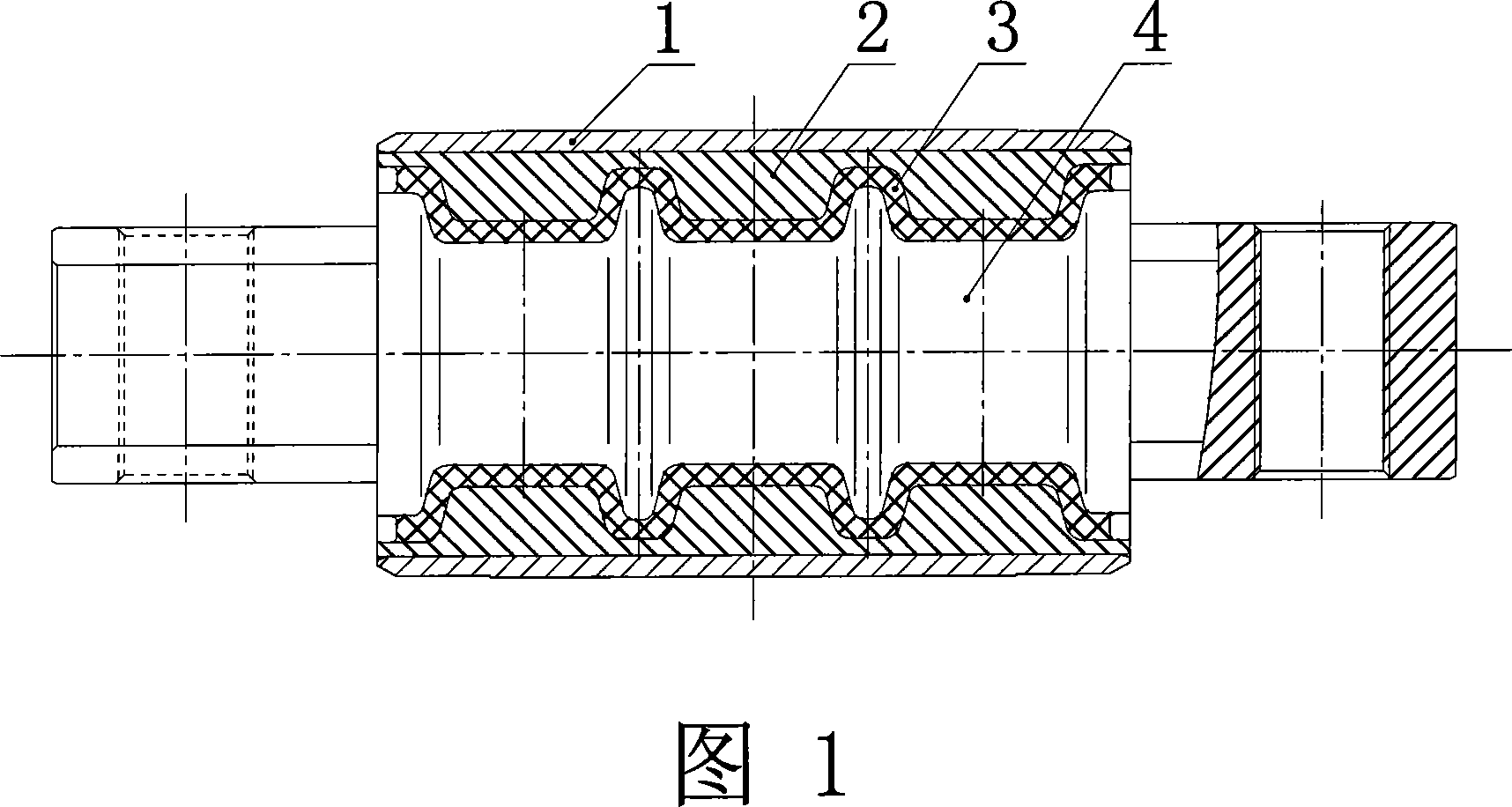
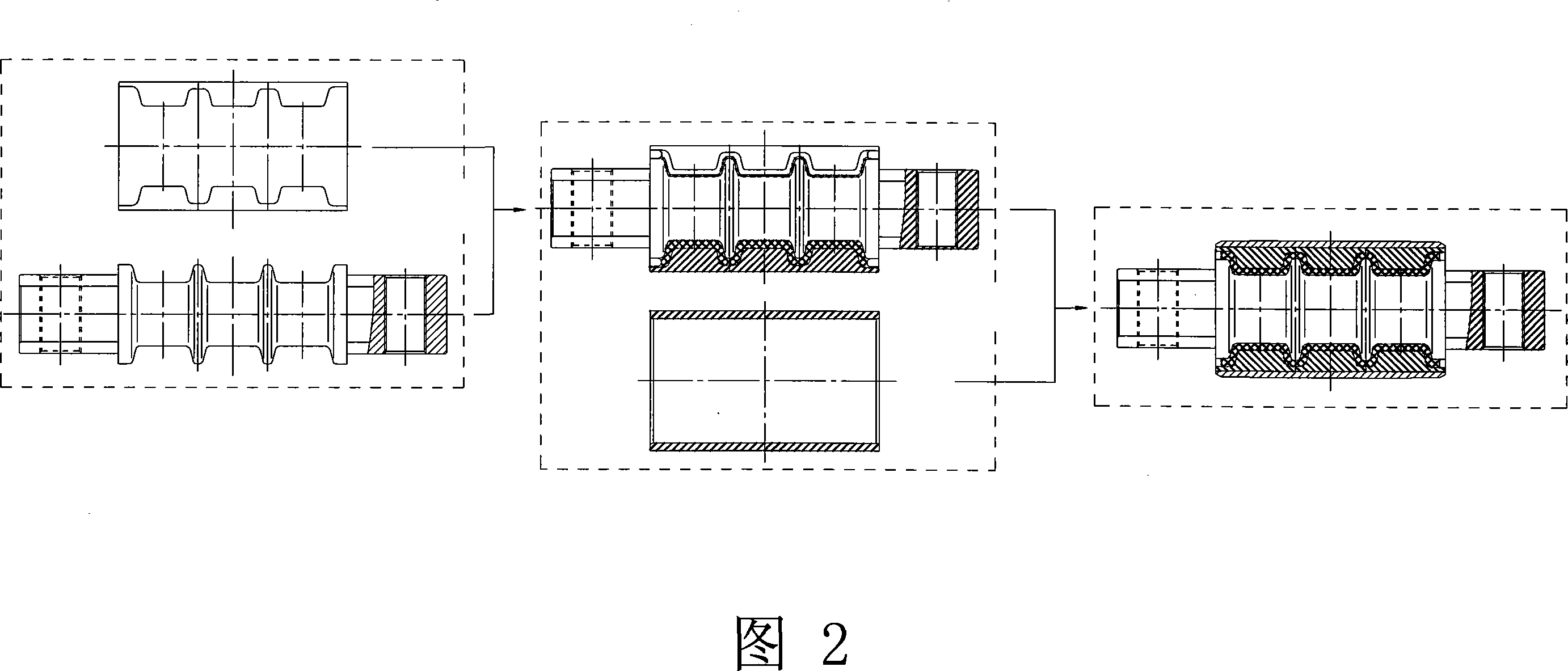
[0020] Figure 1 shows a specific embodiment of the present invention. It can be seen from the accompanying drawings that the present invention is a spherical hinge rubber elastic element, including a metal jacket 1, a mandrel 4 and an elastic rubber 3 body. Its characteristics are: There is a metal spacer 2 between the metal jacket 1 and the elastic rubber body 3. The metal spacer 2 has a two-petal structure, and the metal spacer 2 and the mandrel 4 are in a sawtooth shape. The saw teeth of the two are inlaid and interlocked with each other. Vulcanized together by elastic rubber 3. After being vulcanized, the metal spacer 2 and the elastic rubber body 3 are separated into a rubber metal vulcanized body with gaps in the radial direction compared with the original diameter.

[0021] The production of spherical hing...


PUM


Abstract

A sawtooth modular ball hinge and making and assembling method for the ball hinge are provided. The ball hinge comprises a metallic casing, a core shaft and an elastic rubber element. Between the metallic casing and the elastic rubber element, a metallic partition bushing is provided, which is in 2-flap structure; the metallic partition bushing and the core shaft are in sawtooth shape; the sawteeth of them are mutually nested, engaged and vulcanized together. After the metallic partition bushing and the elastic rubber element are vulcanized, comparing with former diameter, along the radial direction a rubber-metal vulcanizate with a clearance in between is formed. The making of the ball hinge rubber elastic element is: the metallic partition bushing, the core shaft and the elastic rubber are vulcanized under high temperature and pressure into a rubber-metal vulcanizate, then the rubber-metal vulcanizate is pressed into a metallic casing, this forms a finished product. As the rubber-metal vulcanizate is of a 2-flap structure, and is certain distance apart in radial direction comparing with former diameter, when the vulcanizate is pressed into the metallic casing, the rubber is pre-compressed; the pre-compression volume can be adjusted for the rubber by adjusting the apart distance in radial direction of the 2-flap partition bushing.

Description

Technical field [0001] The invention belongs to a vibration damping component and an assembly method thereof, in particular to a spherical hinge type rubber elastic element product and a manufacturing and assembly method thereof. It is mainly used in the rubber elastic elements for the bogies of various locomotives and vehicles, and can also be applied to For any vibration-damping elastic connection parts such as construction machinery. Background technique [0002] Ball hinge rubber elastic element is a commonly used rubber-metal composite vibration damping element, which can be widely used in various damping places, especially in the bogies of rolling stock. The most common applications are three. Large-piece (metal jacket + rubber + mandrel) structure, and this structure has some characteristics, but also has shortcomings, the characteristic is that their performance can basically meet the use of various working conditions, the shortcoming is that when a spherical hinge When t...

Claims


Application Information

Patent Timeline
Patent Type & Authority Applications(China)
IPC IPC(8): F16F1/38
Inventor 张春良
Owner ZHUZHOU TIMES NEW MATERIALS TECH
Learn More