Plasma display manufacturing method

The technology of a plasma display and its manufacturing method is applied in the direction of discharge tube/lamp manufacturing, cold cathode manufacturing, electrode system manufacturing, etc. It can solve the problems of unit board pollution, flying out of glass powder, easy damage of plasma display, etc., and achieve reduction Pollution, Intensity-Increasing Effects

Inactive Publication Date: 2008-01-23
LG ELECTRONICS(NANJING) PLASMA CO LTD
View PDF0 Cites 0 Cited by
  • Summary
  • Abstract
  • Description
  • Claims
  • Application Information

AI Technical Summary

Problems solved by technology

[0013] According to the prior art, in the process of multi-faceting of the plasma display, abrasives are added to the grinding wheel during polishing to adjust the rotation of the grinding wheel and smooth the protruding part of the cutting surface, and glass dust will fly out during this process Foam, causing contamination of the unit board
[0014] Moreover, in the polishing process according to the prior art, heat will be generated due to the friction between the grinding wheel and the glass, and cooling water needs to be added in order to cool the machine. During this process, the cooling water will splash on the unit panel which is very sensitive to moisture, Contamination of the protective film
[0015] Moreover, in the polishing process according to the prior art, as shown in FIG. 2e, since the micro cracks (micro crack) 11a that are likely to cause damage to the unit panel are not completely removed, the plasma display will be impacted by an external force in the subsequent manufacturing process or use. Very fragile

Method used


Image

  • Plasma display manufacturing method
  • Plasma display manufacturing method
  • Plasma display manufacturing method

Examples


Embodiment Construction

[0030] Embodiments of the present invention will be described in detail below with reference to the accompanying drawings.

[0031] FIG. 3 is a schematic diagram of the multi-facet acquisition process in the manufacturing method of the plasma display according to the present invention.

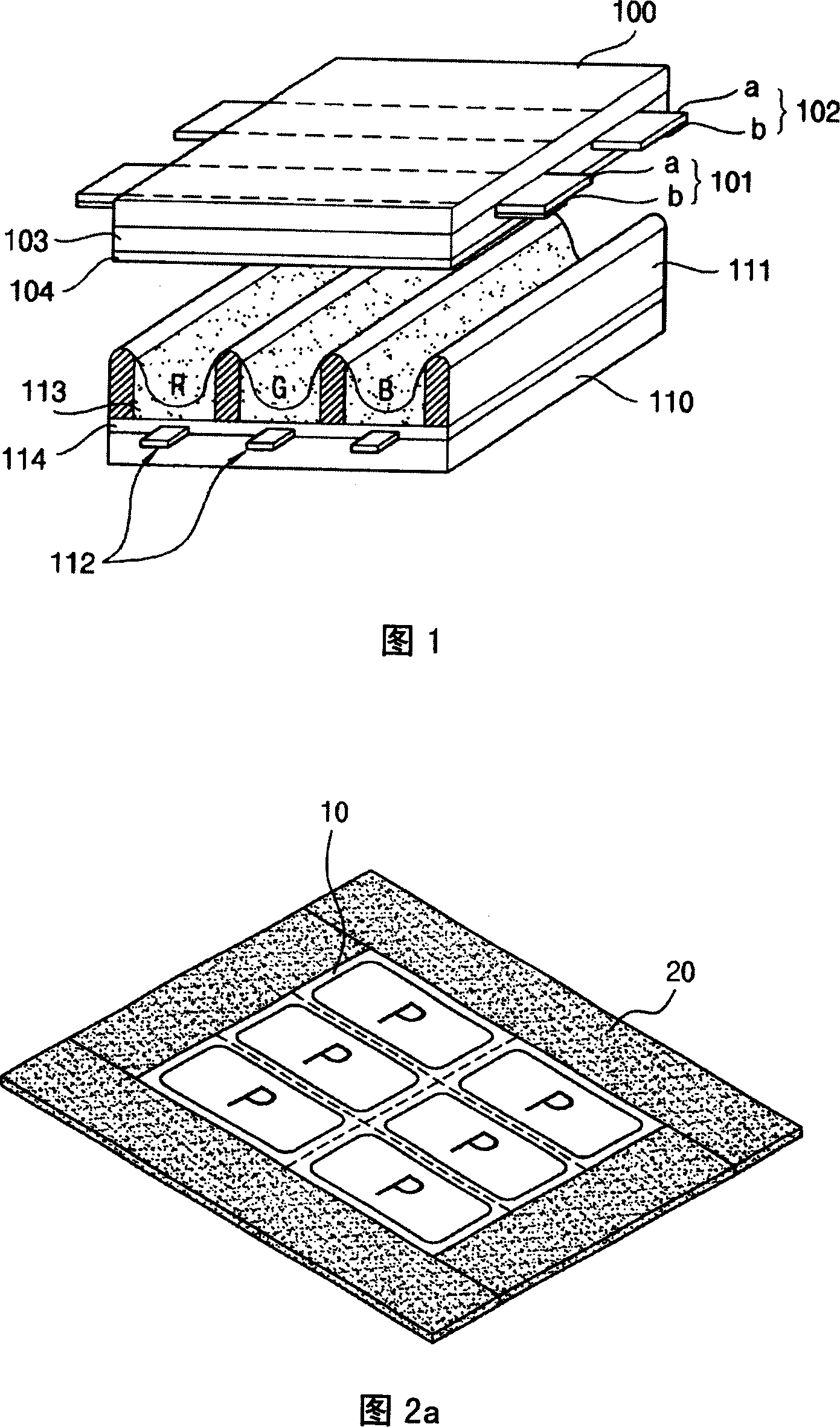
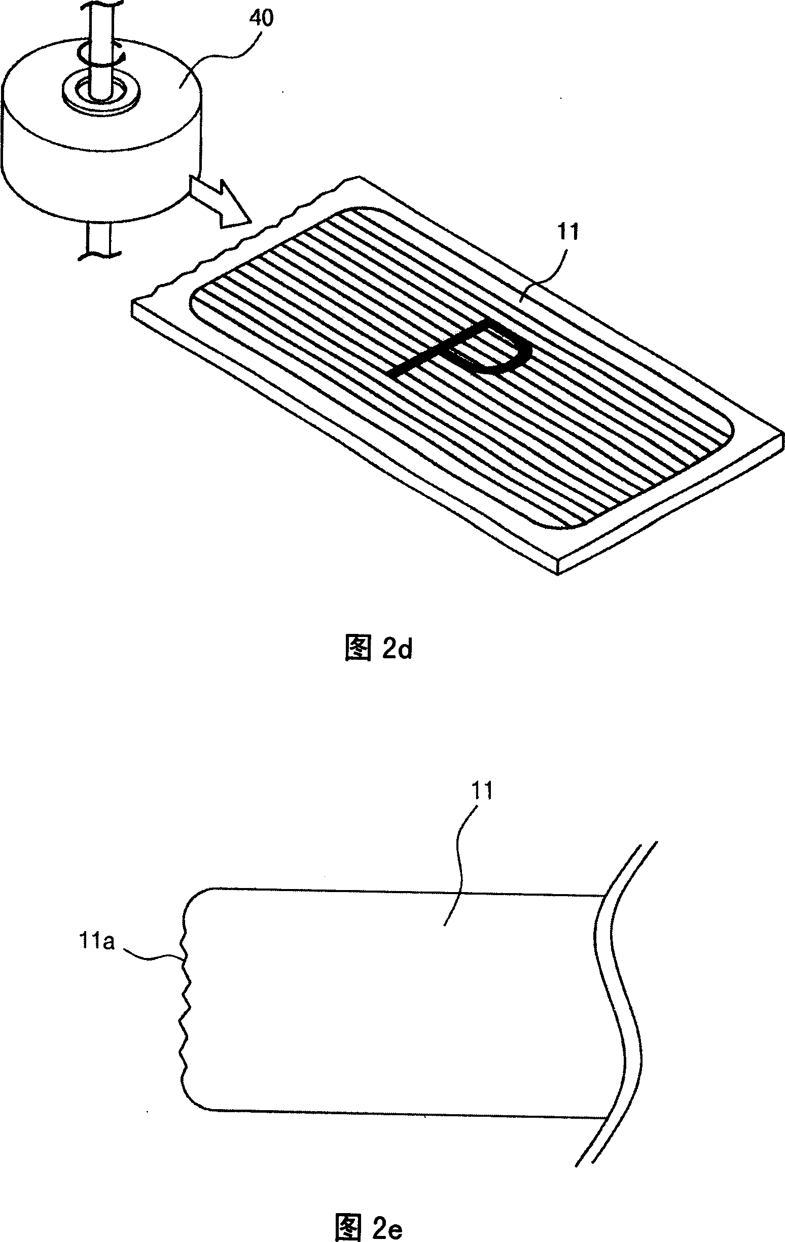
[0032] As shown in Figure 3, according to the multi-face-taking process of the plasma display of the present invention, it consists of several steps: the step of fixing and arranging the mother glass substrate with a guide plate (S10); after fixing and arranging the mother glass substrate, The step of forming a unit panel on the glass substrate (S20); after the unit panel is formed, the step of cutting the mother glass substrate according to the unit panel by a cutter (S30); and the step of heating and polishing the cut surface of the unit panel (S40 ).

[0033] The step of fixing and arranging the mother glass substrate by using the guide plate (S10) is to install the electrode, the dielectr...


PUM


Abstract

The invention relates to a plasma display manufacturing method, which comprises the following procedures: fix and arrange a female glass basal plate with a guide plate; form an unit faceplate on the female glass basal plate after the fixing and arrangement of the female glass basal plate; cut the female glass basal plate according to the unit faceplate with a cutter; heat and polish the cutting plane of the unit faceplate.

Description

technical field [0001] The invention relates to a manufacturing method of a plasma display, in particular to a manufacturing method of a plasma display which improves the multi-faceted display mode and reduces the pollution of the display panel while maintaining safety. Background technique [0002] Generally, a plasma display (Plasma Display Panel: hereinafter referred to as "PDP") is a device for displaying images. After the partition wall formed between the front glass and the back glass made of soda-lime glass constitutes a unit unit, neon (Ne), helium (He) or neon and helium-neon in each unit (Ne+He) is used as the gas for periodic discharge, and a small amount of inert gas such as xenon (Xe) is added to generate discharge through high-frequency voltage. In this case, 147nm vacuum ultraviolet rays (VacuumUltraviolet rays) will be generated, so that the phosphors formed between the partition walls emit light, so that the screen can be displayed. A plasma display is suc...

Claims


Application Information

Patent Timeline
Patent Type & Authority Applications(China)
IPC IPC(8): H01J9/00H01J17/49
Inventor 张铭洙
Owner LG ELECTRONICS(NANJING) PLASMA CO LTD
Why Eureka
Try Eureka