
Instrument board

An instrument panel, one-sided technology, applied in the direction of instruments, instrument parts, lighting devices, etc., can solve the problems of limited alarm strength, occupied space, poor night vision performance, etc., to save occupied space, expand the viewing angle, and high contrast. Effect

Inactive Publication Date: 2008-01-23
李远 +2
View PDF0 Cites 0 Cited by
  • Summary
  • Abstract
  • Description
  • Claims
  • Application Information

AI Technical Summary

Problems solved by technology

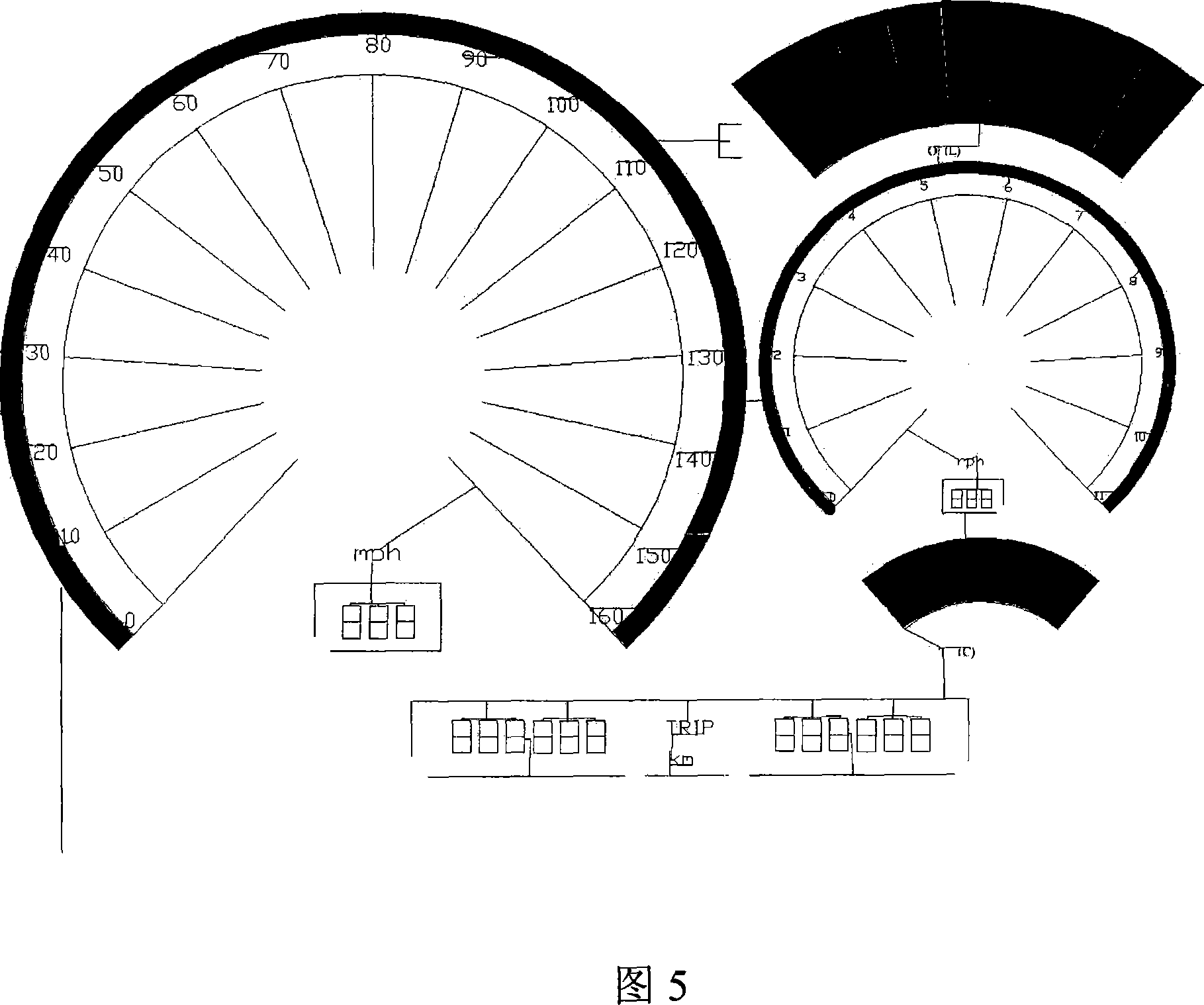
[0003] In order to overcome the disadvantages of the existing locomotive instrument panel, such as high power consumption, large space occupation, limited function, poor night vision performance, and limited alarm force, the present invention provides a transparent electronic instrument panel based on the theory of organic electroluminescence, which not only It can effectively reduce power consumption and power consumption, save space, improve night vision performance, improve the alarm strength for drivers under overspeed, high speed, low fuel and idling conditions, and achieve high contrast, extended viewing angle, thin and light design purpose

Method used


Image

  • Instrument board
  • Instrument board
  • Instrument board

Examples


Embodiment Construction

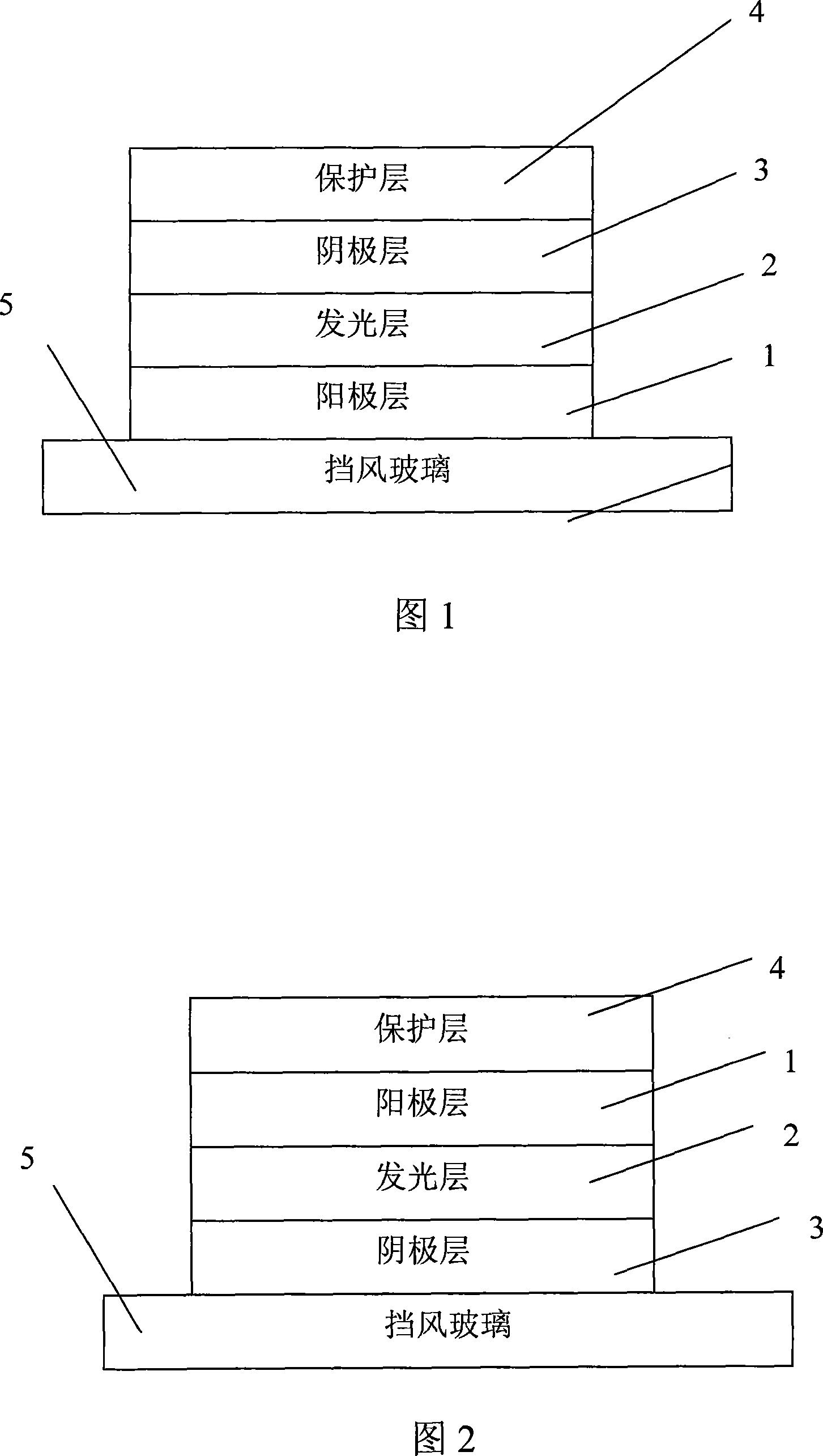
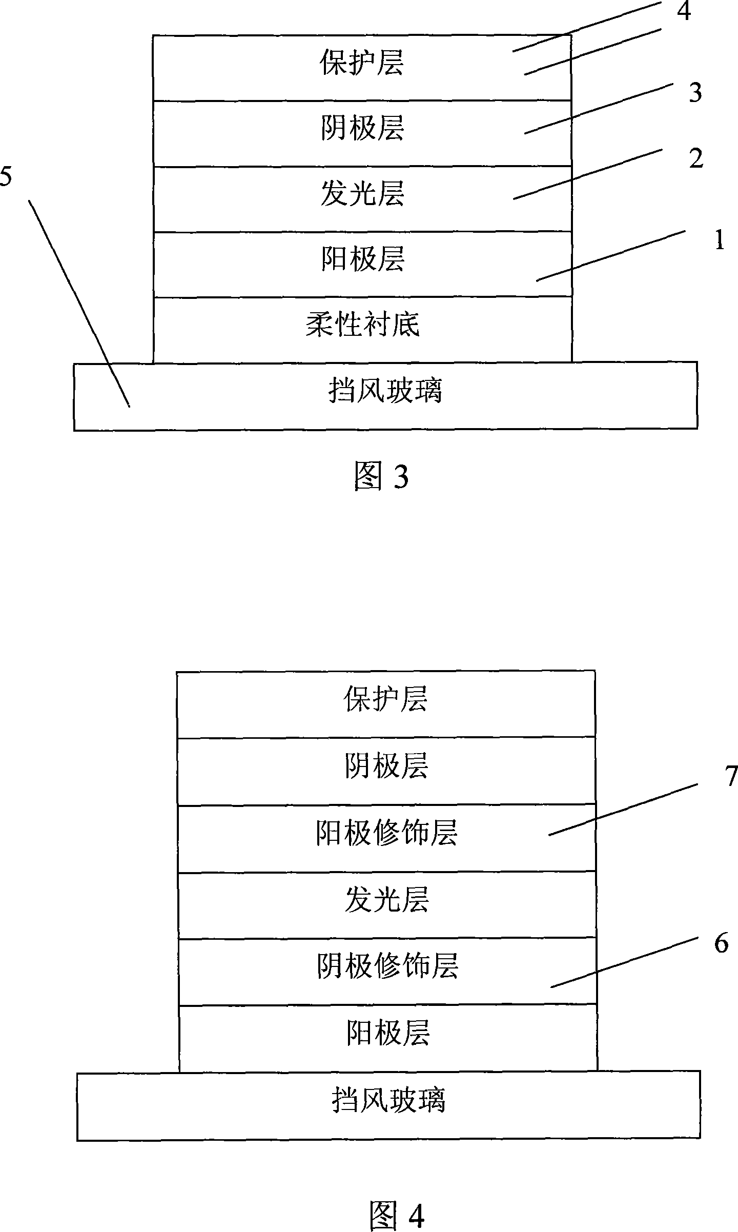
[0022] Embodiments of the present invention will be described in detail below in conjunction with the accompanying drawings. As shown in Fig. 1 and Fig. 2, they are structural schematic diagrams of two embodiments of the instrument panel of the present invention. The instrument panel includes an anode layer 1, a luminous layer 2, a cathode layer 3 and a protective layer 4, wherein the lowermost layer can be the anode layer 1 (as shown in Figure 1) or the cathode layer 3 (as shown in Figure 2) , the luminescent layer 2 is sandwiched between the anode layer 1 and the cathode layer 3, and the uppermost layer can further add a protective layer 4 to protect the cathode layer or anode layer as the electrode layer from external wear and damage. The anode layer and the cathode layer are respectively provided with electrode patterns of different shapes on the side facing the light-emitting layer. During operation, the electrode patterns of the anode layer and the cathode layer are resp...


PUM

PropertyMeasurementUnit
Thicknessaaaaaaaaaa

Abstract

The present invention discloses an instrument panel, which comprises an anode layer, a luminescent layer and a cathode layer, wherein the luminescent layer is imbedded between the anode layer and the cathode layer, an electrode pattern with different shapes corresponding to the driving instrument panel indication is respectively arranged on one surface of the anode layer and the cathode layer opposite to luminescent layer, the material of the luminescent layer (2) can be chosen from one of the NPB, ALQ3 Irppy: PVK and the DCJTB: Rubrene: PVK, or from the random combination of the material; the thickness of the instrument panel is at an micron order .When the instrument panel works, the electrode patterns of the anode layer and the cathode layer are respectively connected with a positive power supply and a negative power supply, to lead to the luminescence of the corresponding region of the luminescent layer imbedded between the anode layer and the cathode layer, thus indicating the driving condition of vehicle. The design of the instrument panel is thin and light, not only effectively reducing the electricity consumption and the power consumption, but promoting the night vision performance, widens the horizon, and saves a lot of cab space.

Description

technical field [0001] The present application relates to an instrument panel, in particular to an electronic instrument panel for locomotives based on the theory of organic electroluminescence. Background technique [0002] At present, the instrument panel widely used in the locomotive field is a mechanical pointer instrument indicating device made of metal alloy and organic plastic controlled by a circuit. However, this traditional instrument panel consumes a lot of power and takes up a lot of space, which limits the size of the airbag and the buffering distance after inflation, and the traditional instrument panel has poor visibility at night, and it is difficult to , too high speed, too low oil quantity and idling speed, etc., the alarm to the driver is limited, and the indication function cannot be fully exerted. Contents of the invention [0003] In order to overcome the disadvantages of the existing locomotive instrument panel, such as high power consumption, large...

Claims


Application Information

Patent Timeline
IPC IPC(8): H05B33/00G12B11/00
Inventor 李远宋晶路薛单
Owner 李远
Learn More