Trussed-beam roomage embankment and wall structure

A wall structure and truss-type technology, which is applied in underwater structures, infrastructure engineering, water conservancy projects, etc., can solve problems such as inability to be used for emergency use, obstruction of species movement routes, and landscape improvement, so as to increase water and soil conservation functions, Fast and easy construction, beneficial to ecological development

Inactive Publication Date: 2010-06-09
黎彪钦
View PDF4 Cites 0 Cited by
  • Summary
  • Abstract
  • Description
  • Claims
  • Application Information

AI Technical Summary

Problems solved by technology

In addition, they have the following common characteristics: first, they have a single function, that is, they have no other functions except for safety and maintenance; As a result, its landscape is impoverished. Even if it is shaped with a modeling template, it is difficult to improve the landscape.
The third is field casting. Both types of structures must combine steel bars and templates on site and then cast concrete, which is easily affected by the weather and slow down the construction speed. The fourth is the blocking effect. The higher the height, the more obvious it is; the fifth is the difficulty in repairing damage, such as partial wall or foundation damage, it is difficult to have a good method to completely repair it; the sixth is that it cannot be used for emergency use. From the perspective of the construction process of dikes and walls, it is necessary to repair them. Impossible as an emergency protective measure
[0003] Multi-faceted is the future direction of embankment and wall structure technical design thinking. Even if the same structural form has multiple purposes, the current commonly used cantilever or gravity embankment and wall structures basically take safety maintenance as the main axis of their design , there are few other uses and purposes, resulting in a single use, a monotonous landscape plan, and blocking the movement routes of species, making communication difficult, and because it can only be cast in the field due to the relationship between construction and material properties, it cannot be used as an emergency site. use

Method used


Image

  • Trussed-beam roomage embankment and wall structure
  • Trussed-beam roomage embankment and wall structure
  • Trussed-beam roomage embankment and wall structure

Examples


Embodiment Construction

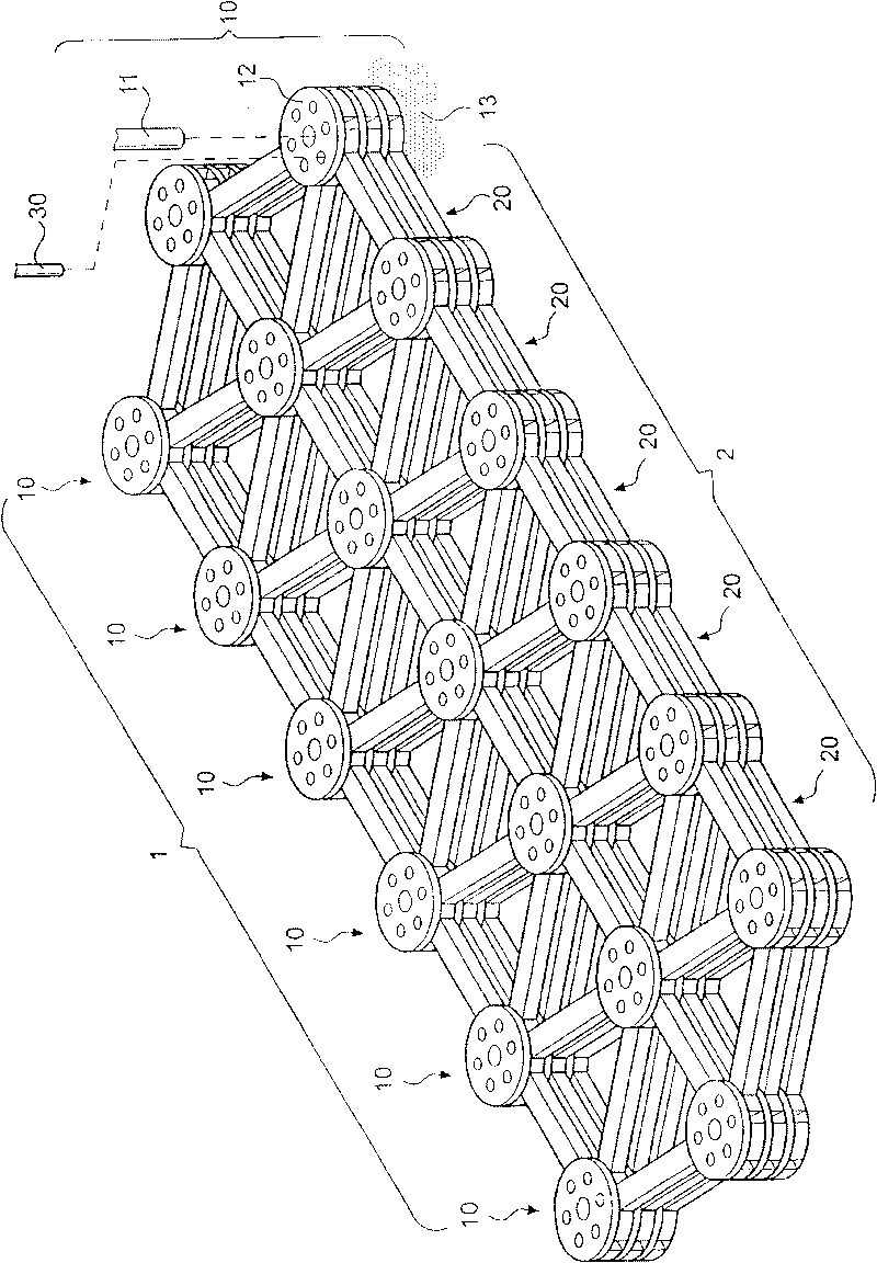
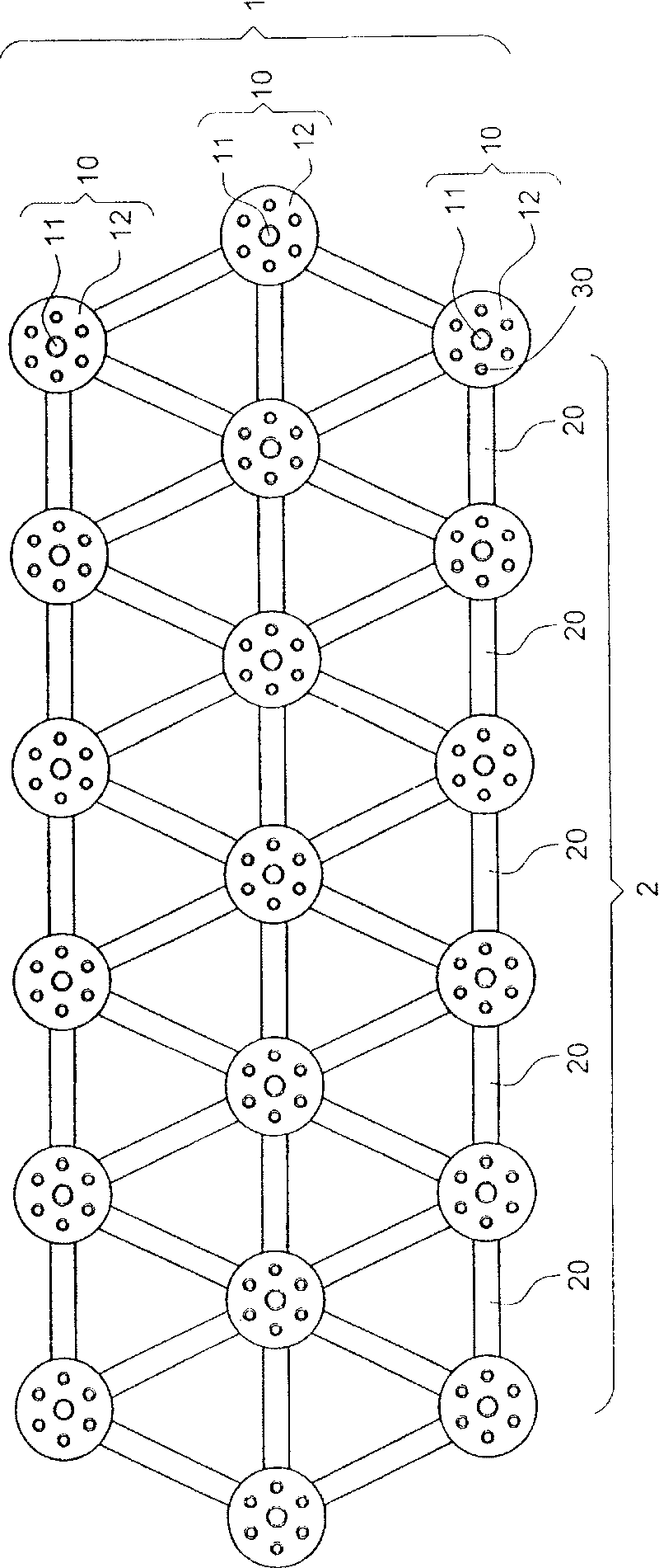
[0047] First, see figure 1 and figure 2 As shown, it is a three-dimensional schematic diagram and a top view of the first possible embodiment of the truss type space embankment and wall structure of the present invention, which includes:

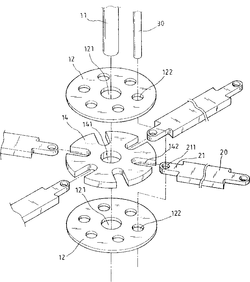
[0048] A cantilever structure group 1, each of which cantilever structure 10 is composed of an anchor support column 11 and a multi-directional connecting plate 12, wherein, the anchor support column 11 is anchored on the supporting ground or base 13 , to form the support of the cantilever structure, and the upper part is assembled with at least one multidirectional connecting plate 12 to form a node structure such as a truss node;

[0049] A group of rods 2, any one of the rods 20 connects its two ends with the joints as a whole with the joint 30 to form a hinge effect, and is combined with each other accordingly to make its overall structure a space embankment in the form of a truss, wall structure.

[0050] The cantilever structure gr...


PUM


Abstract

The invention relates to a truss type space embankment and wall structure, comprising a cantilever structure group and a member bar group. Each cantilever structure in the cantilever structure group consists of a guy anchor support column and a multidirectional web, the guy anchor support column is to arrange a guy anchor at the lower part on a supporting stratum or a base, thus forming the bearing of the cantilever structure and the upper part is assembled with the multidirectional web to form a knot structure similar to the function of a truss knot; two ends of each member bar in the memberbar group are integrated with the knot by a binding part, therefore, a hinging function is formed and after the mutual combination, the whole structure becomes a truss type space embankment and wall structure. The invention can not only achieve the purpose of safe maintenance, but also protect and improve the environment, enhance landscape effect and be beneficial to ecological development.

Description

technical field [0001] The invention relates to a truss type space dike and wall structure. Background technique [0002] The cantilever or gravity structure is the most commonly used wall and embankment structure in civil engineering. The gravity structure uses its own weight to bear the overturning moment and horizontal thrust generated by external forces, while the cantilever structure uses its cantilever characteristics to resist the overturning moment caused by external force, and at the same time resist the horizontal thrust generated by external force by the weight of the overall structure and the friction force generated by the backfill weight at the bottom of the foundation. These two structures are both planar structures in mechanics . In addition, they have the following common characteristics: first, they have a single function, that is, they have no other functions except for safety and maintenance; As a result, its landscape is impoverished. Even if it is sha...

Claims


Application Information

Patent Timeline
Patent Type & Authority Patents(China)
IPC IPC(8): E02D29/02E02B3/04
Inventor 黎彪钦
Owner 黎彪钦
Why Eureka
Try Eureka