Piezoelectric drive device and liquid discharging device
A technology of piezoelectric drive and drive device, which is applied in the direction of liquid variable capacity machinery, generator/motor, piezoelectric effect/electrostrictive or magnetostrictive motor, etc., which can solve difficult configuration and difficult to satisfy cam drive, etc. Problems, to achieve the effect of easy miniaturization and thinning, high-speed drive
- Summary
- Abstract
- Description
- Claims
- Application Information
AI Technical Summary
Problems solved by technology
Method used
Image
Examples
no. 1 Embodiment approach
[0054] Hereinafter, embodiments of the present invention will be described with reference to the drawings.
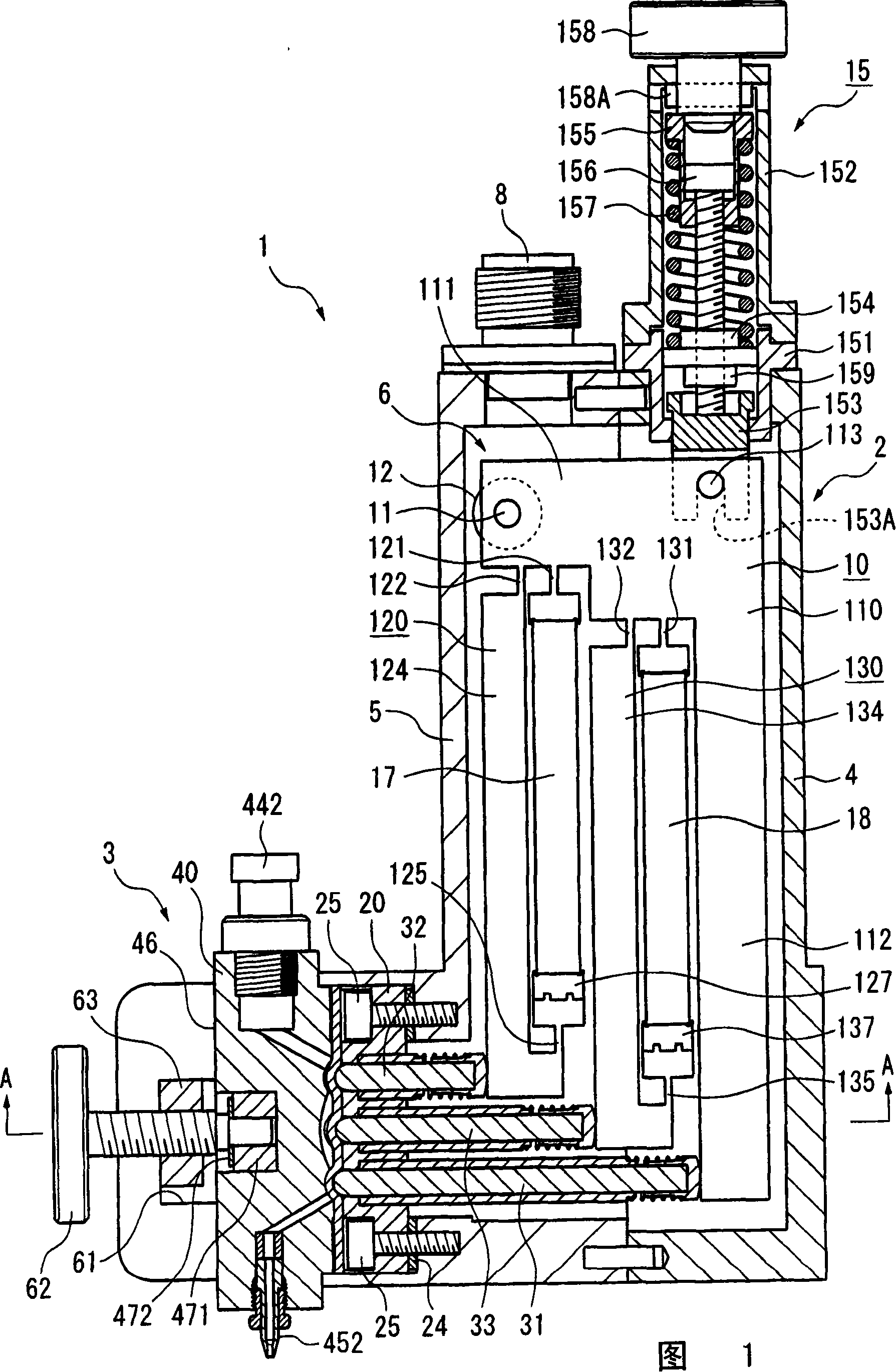
[0055] FIG. 1 shows a liquid discharge device 1 of the present embodiment. In addition, in the following description, for convenience, the upper side in FIG. 1 is described as the upper side and the lower side is described as the lower side. However, the orientation of the liquid discharge device 1 when used is not limited to that shown in FIG. Use it facing horizontally or upside down.
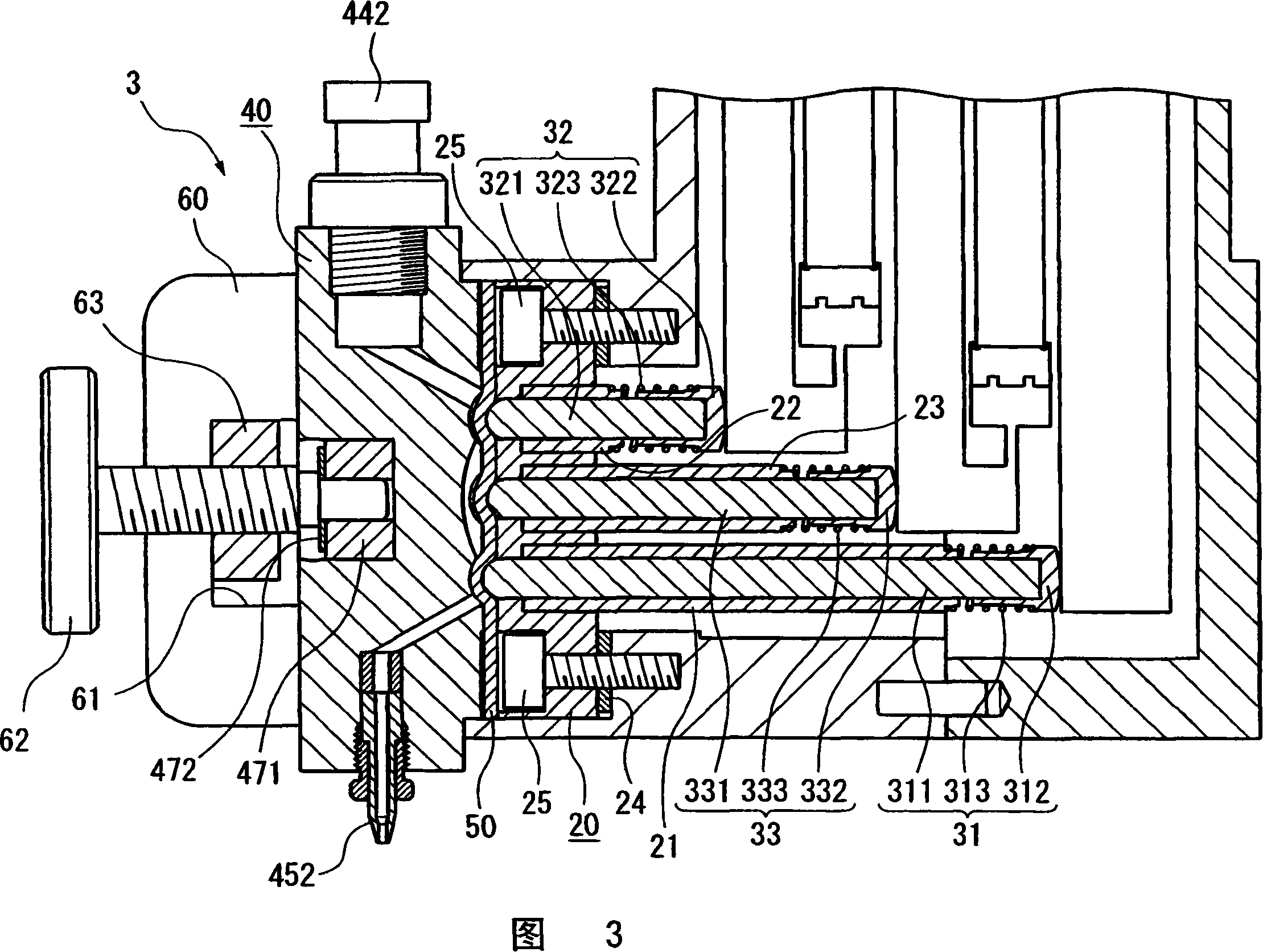
[0056] The liquid discharge device 1 is a diaphragm pump and includes a piezoelectric drive device 2 and a pump unit 3 of the liquid discharge device 1 .
[0057] [Structure of piezoelectric actuator]
[0058] The piezoelectric drive device 2 includes a drive unit case 4 , a pump case 5 screwed to the drive unit case 4 , and a drive unit main body 6 .
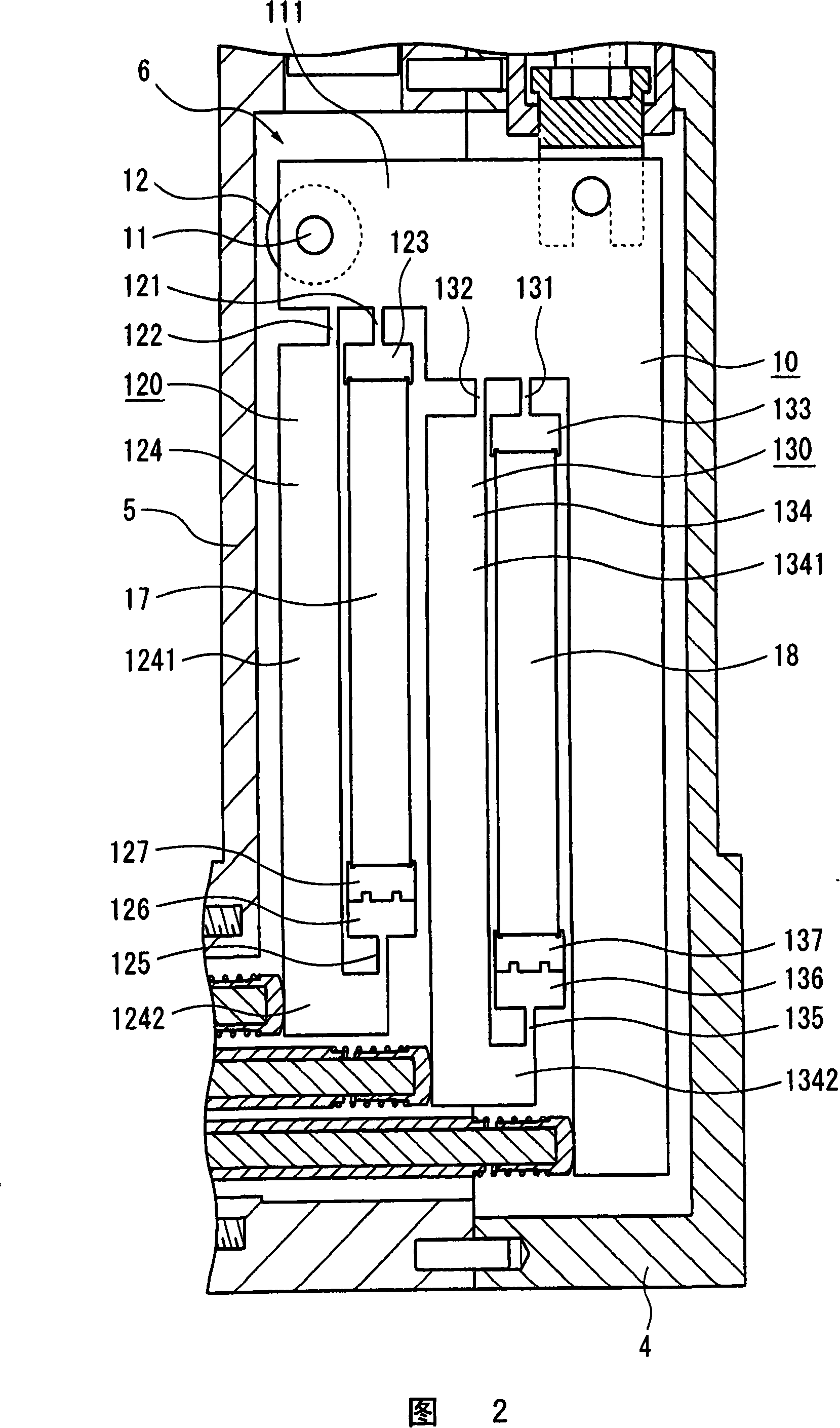
[0059] The driving device main body 6 includes a displacement amplifying plate 10 built in the housings 4 and 5 , an urging mechani...
no. 2 Embodiment approach
[0182] Hereinafter, a second embodiment of the present invention will be described with reference to FIGS. 17 to 19 . In addition, in each of the following embodiments, the same reference numerals are assigned to the same or similar configurations as those of the above-described embodiments, and descriptions thereof are omitted or simplified.
[0183] The liquid discharge device 1B of the second embodiment is a tube pump in which a tube 710 is used instead of the diaphragm 50 . Furthermore, there are some differences in the structure or shape of the first to third pressing members 31B to 33B, the displacement amplifying plate 10B, and the urging mechanism 15B for pressing the tube 70 from those of the first embodiment, but their operations are similar to those of the first embodiment. 1 The embodiment is the same.
[0184] The displacement amplifying plate 10B has basically the same structure as the displacement amplifying plate 10 described above. However, the first hinge p...
PUM
 Abstract
Description
Claims
Application Information
 - R&D
- Intellectual Property
- Life Sciences
- Materials
- Tech Scout
- Unparalleled Data Quality
- Higher Quality Content
- 60% Fewer Hallucinations
Browse by: Latest US Patents, China's latest patents, Technical Efficacy Thesaurus, Application Domain, Technology Topic, Popular Technical Reports.
© 2025 PatSnap. All rights reserved.Legal|Privacy policy|Modern Slavery Act Transparency Statement|Sitemap|About US| Contact US: help@patsnap.com


