
Packet transmission device and control method thereof

A technology of packet transmission and control method, applied in transmission systems, digital transmission systems, data exchange networks, etc., can solve the problems of expensive high-performance conversion cards and increased development costs, and achieve easy business startup, shorten the development period, and effectively Effects of using existing resources

Inactive Publication Date: 2008-02-06
FUJITSU LTD
View PDF1 Cites 2 Cited by
  • Summary
  • Abstract
  • Description
  • Claims
  • Application Information

AI Technical Summary

Problems solved by technology

However, since such a high-performance conversion card is expensive, there is a problem that the development cost increases

Method used


Image

  • Packet transmission device and control method thereof
  • Packet transmission device and control method thereof
  • Packet transmission device and control method thereof

Examples


Embodiment approach 1

[0070] Now will be described in accordance with the present invention in the following order with reference to FIGS. 1, 2, 3A, 3B, 4, 5A to 5C, 6, 7, 8A, 8B, 9 to 11, 12A to 12C, 13A to 13C, 14 and 15 Implementation of the packet transmission device and its control method [1] and [2]:

Embodiment approach 1

[0071] I. Implementation [1]: Figures 1, 2, 3A, 3B, 4, 5A to 5C, 6, 7, 8A, 8B and 9

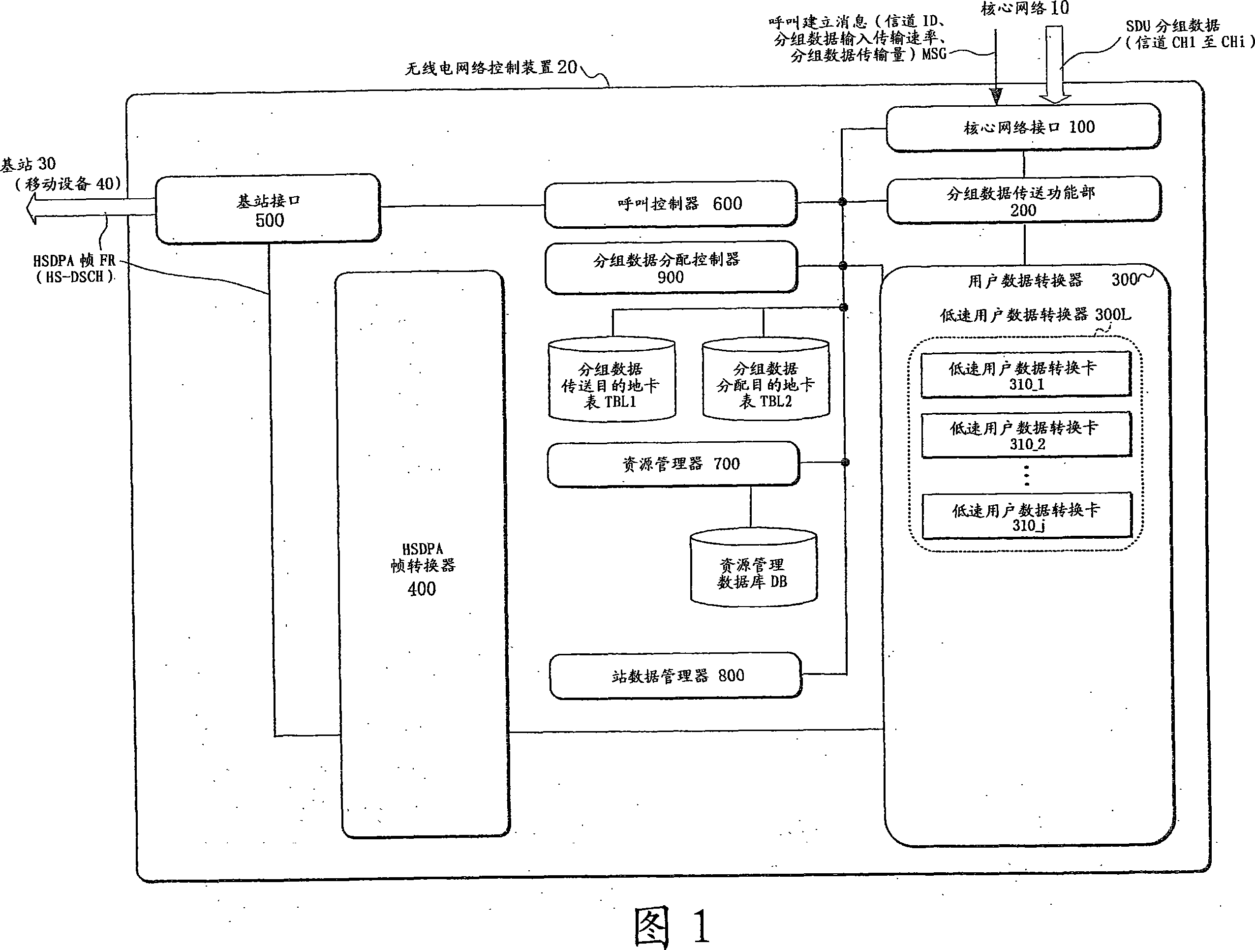
[0072] I.1. Configuration: Figure 1

[0073] I.2. Example of operation: Figures 2, 3A, 3B, 4, 5A to 5C, 6, 7, 8A, 8B and 9

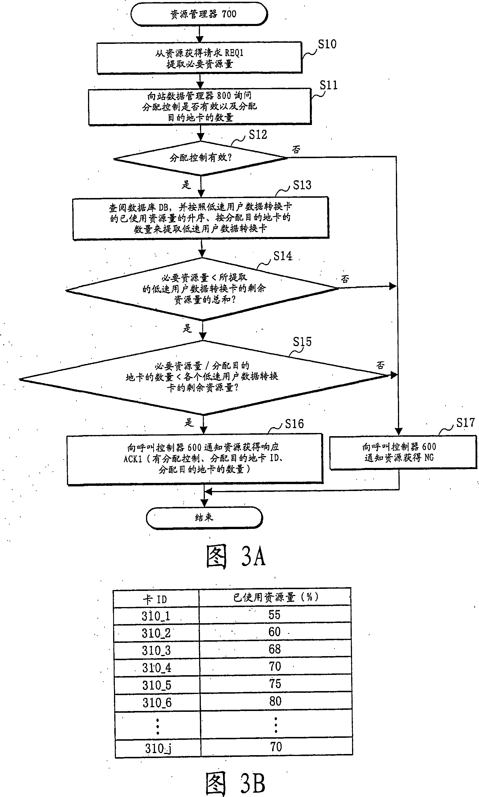
[0074] I.2.1. Examples of packet data distribution destination setting: Figures 2, 3A, 3B, 4 and 5A to 5C

Embodiment 1

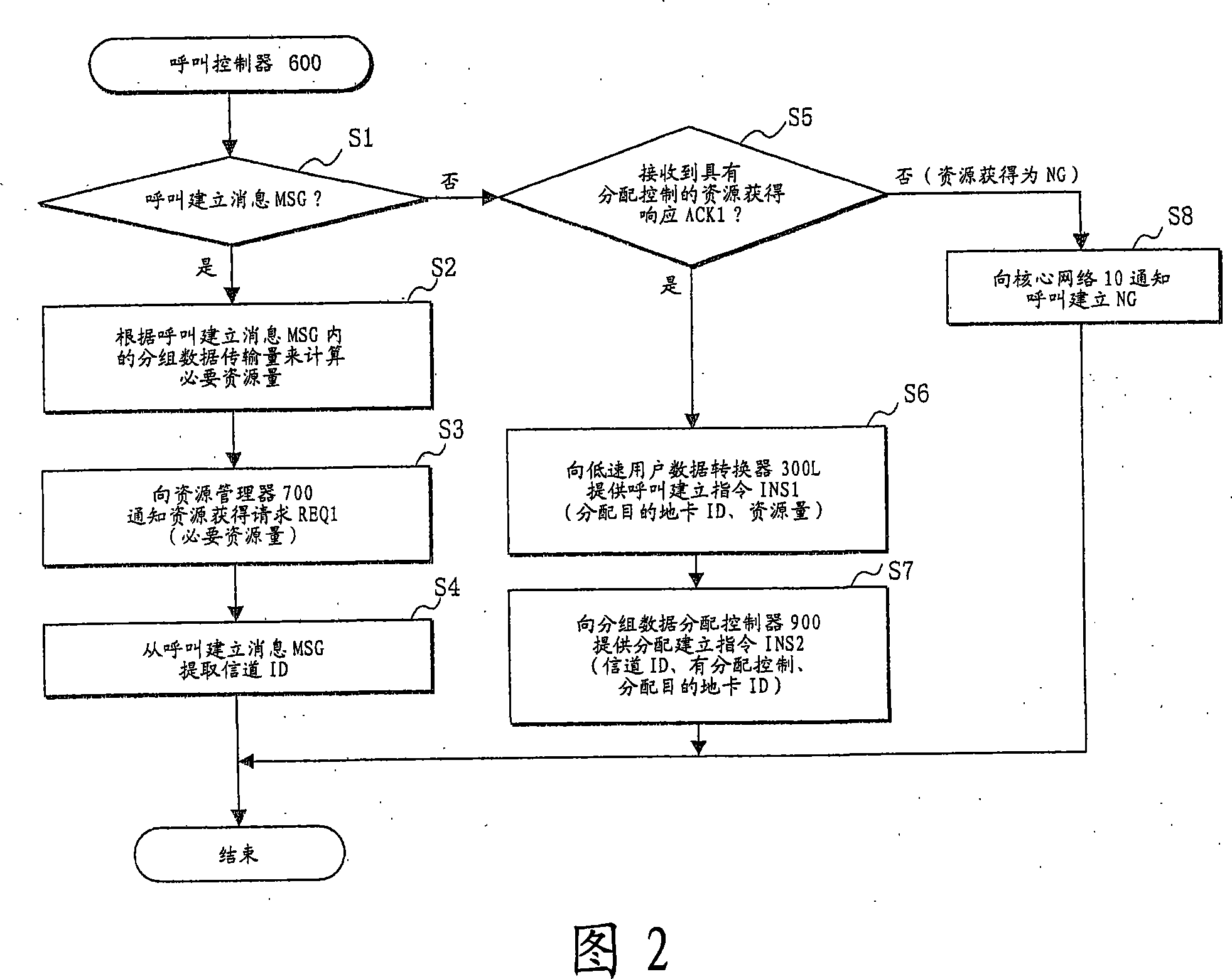
[0075] I.2.1.1. Operation example of call controller 600 [1]: Figure 2


PUM


Abstract

In a packet transmission device and control method thereof which can improve the transmission rate of a packet without adding a high speed user data-conversion card, when packet data is inputted through a single arbitrary channel among a plurality of channels, from among a predetermined number of low speed user data-conversion cards provided common to the plurality of channels, the low speed user data-conversion cards by a number corresponding to a ratio between an output transmission rate of the low speed user data-conversion card and an input transmission rate of the packet data are extracted. The packet data is sequentially and cyclically distributed to the low speed user data-conversion cards extracted. Predetermined length user data outputted from the low speed user data-conversion cards are converted into a frame of HSDPA (High Speed Downlink Packet Access) system and multiplexed into a single channel HS-DSCH (High Speed Downlink Shared Channel) to be outputted.

Description

Technical field [0001] The present invention relates to a packet transmission device and a control method thereof, and more particularly to a packet transmission device and a control method thereof for dividing input packet data into user data of a predetermined length to output it. Background technique [0002] The prior art embodiments [1] and [2] of the packet transmission technology as described above will now be described with reference to FIGS. 16 to 18. [0003] The radio communication system 1 shown in FIG. 16 represents the configuration of a system to which the prior art embodiments [1] and [2] are applied, and the system includes a core network 10 and two radio network control devices 20_1 connected to the core network 10 And 20_2 (hereinafter sometimes denoted as reference number 20), four base stations 30_1 to 30_4 (hereinafter sometimes denoted as reference number 30) managed by the radio network control device 20, and a call connected to the radio network control d...

Claims


Application Information

Patent Timeline
Patent Type & Authority Applications(China)
IPC IPC(8): H04L12/56H04W28/00H04L47/43H04W28/06
CPCH04W28/06
Inventor 尼崎富士大石雄一郎
Owner FUJITSU LTD
Learn More