
Vibration damping bracket

A technology of bracket and vibration direction, applied in the direction of shock absorber, spring/shock absorber design features, shock absorber, etc., can solve the problem of vibration noise reduction effect and so on

Inactive Publication Date: 2008-02-06
KOBE STEEL LTD
View PDF0 Cites 2 Cited by
  • Summary
  • Abstract
  • Description
  • Claims
  • Application Information

AI Technical Summary

Problems solved by technology

However, if the cause of the vibration noise is the forced vibration caused by the vibration of the vibrating equipment, even if the natural frequency of the dynamic vibration absorber is adjusted to the excitation frequency, the phase of the displacement and force generated by the viscoelastic body deviates, so the dynamic vibration absorber The force generated will not be completely opposite to the phase of the excitation force, so the displacement of the installation point of the dynamic vibration absorber is not zero, and the vibration and noise reduction effect is poor

Method used


Image

  • Vibration damping bracket
  • Vibration damping bracket
  • Vibration damping bracket

Examples


no. 1 Embodiment approach

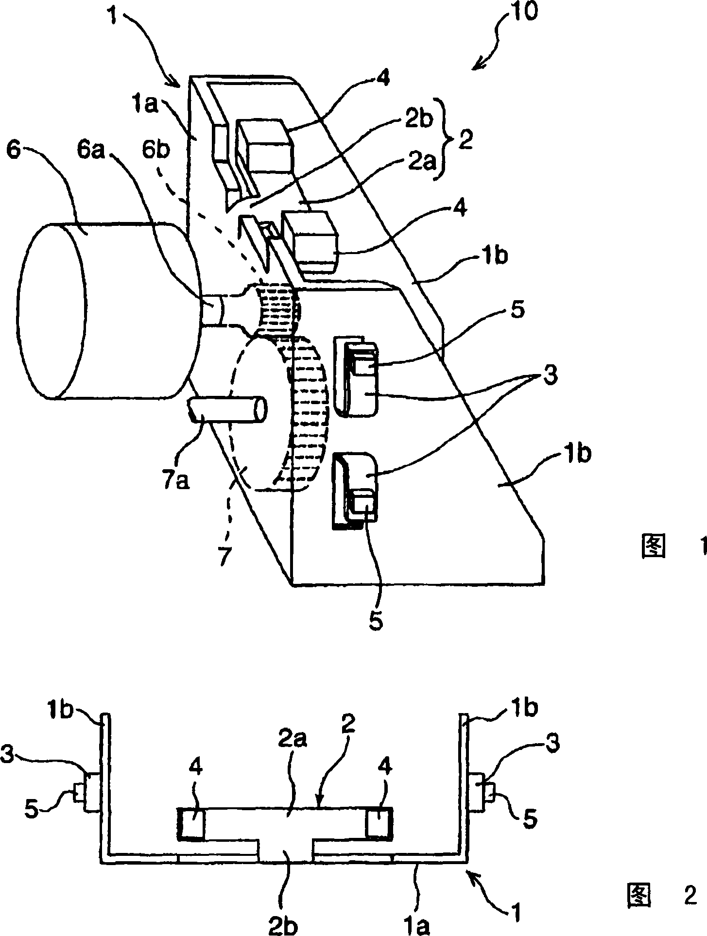
[0025] The damping bracket 10 (hereinafter referred to as bracket) of the present embodiment is suitable for fixing the rotary motor 6 (vibration equipment) and the gear 7 used in OA (office automation) equipment, AV (audio-visual) equipment, etc., for example. This rotary motor 6 has a rotary shaft 6a and a gear 6b ​​provided at the end of the rotary shaft 6a. In addition, the gear 7 is provided so as to mesh with the gear 6b ​​of the swing motor 6, rotates by the rotation of the gear 6b, and transmits the driving force of the swing motor 6 to other devices not shown in the figure.

[0026] The bracket 10 is composed of, for example, a single steel plate (bracket component), and has a frame body 1 (bracket main body) and dynamic vibration absorbers 2 and 3 (vibration absorbing parts). The frame body 1 is formed by bending the steel plate into a U-shape as shown in FIGS. 1 and 2 , and has a substantially rectangular rear surface 1a and substantially trapezoidal side surfaces 1...

no. 2 Embodiment approach

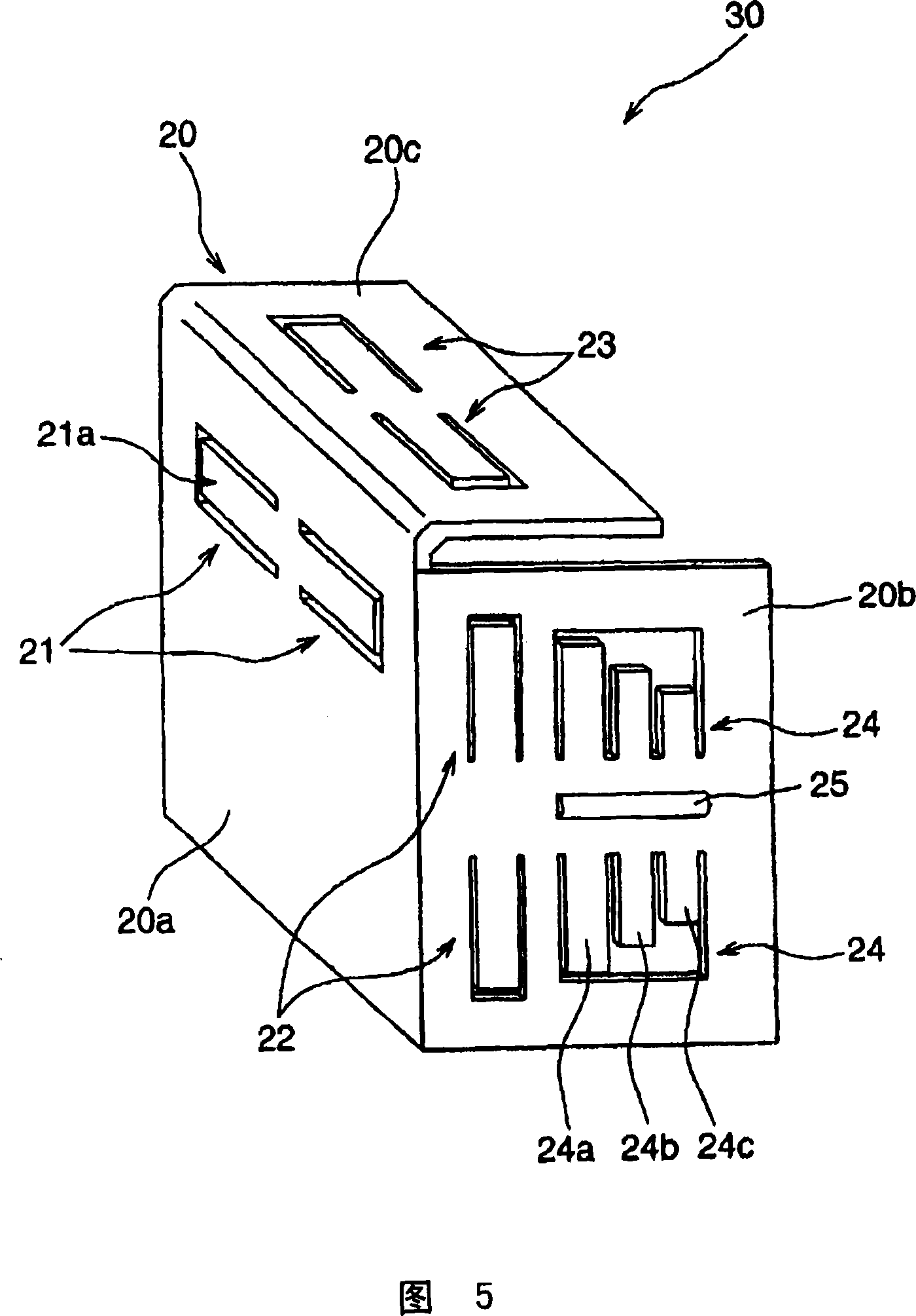
[0060] Next, a second embodiment of the present invention will be described. The dynamic vibration absorbers 2 and 3 of the vibration-damping bracket 10 of the first embodiment are formed by forming cutouts on the frame body 1 and bending them, but the dynamic vibration absorbers of the vibration-damping bracket 30 of the present embodiment are as shown in FIG. 5, it is formed by forming a slit on the frame body 20. In addition, in FIG. 5, the rotation motor 6 etc. which are provided in the back surface 20a are abbreviate|omitted.

[0061] The frame body 20 is formed by bending one steel plate, and is composed of a rear surface 20a, a side surface 20b perpendicular to the rear surface 20a, and an upper surface 20c. On the back surface 20a, dynamic vibration absorbers 21, 21 for reducing vibration generated in a direction perpendicular to the back surface 20a are provided. That is, the dynamic vibration absorber 21 is formed by forming a notch in a portion of the steel plate ...


PUM


Abstract

To reduce the vibration and noise of a bracket resulting from the forced excitation force of a vibrating apparatus and also shorten manufacturing time by saving labor for manufacture. [MEANS FOR SOLVING PROBLEMS] This vibration reducing bracket comprises a frame body (1) fixing a rotating motor (6) and dynamic vibration absorbers (2) and (3) formed by slitting a part of the frame body (1) and raising it while bending. The vibration reducing bracket is so formed that the vibration parts (2a) and (3a) of the dynamic vibration absorbers (2) and (3) can be vibrated in the vibrating direction of the frame body (1) vibrated by the rotating motor (6).

Description

technical field [0001] The present invention relates to a vibration-damping bracket for reducing noise and the like by attenuating vibration of a bracket for fixing vibrating equipment. Background technique [0002] AV and OA equipment such as DVD (Digital Versatile Disc) and printers use high-speed rotating parts such as motors, gears, and HDD (Hard Disk Drive). In recent years, by increasing the rotation speed of these motors and gears, the speed and performance of AV and OA equipment have been increased. However, the increase in vibration associated with this will lead to deterioration of the reading accuracy of DVDs and damage caused by the equipment. An increase in the noise produced. Therefore, it is desired to reduce vibration noise generated by a motor or the like rotating at a high speed. [0003] As a dynamic vibration absorber for reducing such vibrations, there is a dynamic vibration absorber in which a weight and a viscoelastic body are integrally formed and a...

Claims


Application Information

Patent Timeline
Patent Type & Authority Applications(China)
IPC IPC(8): F16F15/02
CPCF16F2230/36F16F7/104F16F15/02F16F15/00
Inventor 杉本明男山口善三
Owner KOBE STEEL LTD
Features
  • Generate Ideas
  • Intellectual Property
  • Life Sciences
  • Materials
  • Tech Scout
  • Unparalleled Data Quality
  • Higher Quality Content
  • 60% Fewer Hallucinations
Learn More