

Optical lens for imaging
An optical mirror and imaging technology, applied in the field of optical mirror groups, can solve the problems of reduced lens thickness, poor lens uniformity, and difficulty in placing three lenses in this space.
Active Publication Date: 2008-02-13
LARGAN PRECISION
View PDF0 Cites 6 Cited by
- Summary
- Abstract
- Description
- Claims
- Application Information
AI Technical Summary
Problems solved by technology
[0003] The current mobile phone lens, in order to consider the correction of aberration, mostly adopts three lens structures, the most common of which is the positive and negative triplet type. However, when the height of the lens is reduced from 5mm to 3mm, the volume of the imaging system is reduced, making the It becomes difficult to place three lenses in this space, and the thickness of the lens must be reduced, which makes the material uniformity of the lens made of plastic injection molding poor.
Method used
View moreImage
Smart ImageViewing Examples

Examples
Embodiment 1
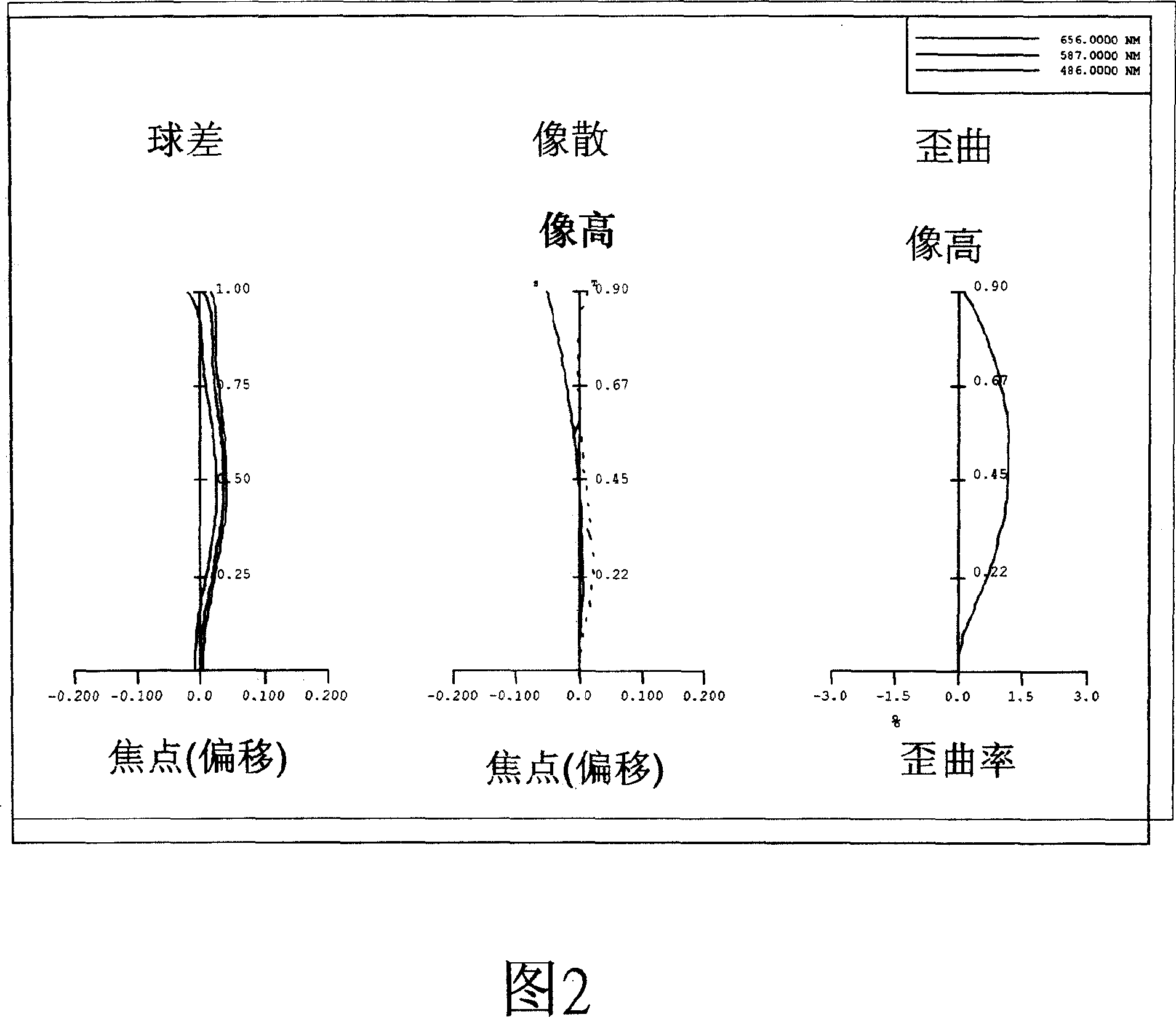
[0066] f (focal length) = 1.53mm Fno = 2.8, HFOV (half angle of view) = 30.2deg.
[0067]
[0068] Table 1
[0069] Aspheric coefficient
[0070] Table 2
[0071] (Embodiment 2 Implementation 2)
[0072] F (focal length) = 1.38mm, Fno = 2.8, HFOV (half angle of view) = 33.0deg.
[0073]
[0074] table 3
[0075] Aspheric coefficient
[0076] Table 4
[0077] Embodiment one
[0078] table 5
Login to View More PUM
 Abstract
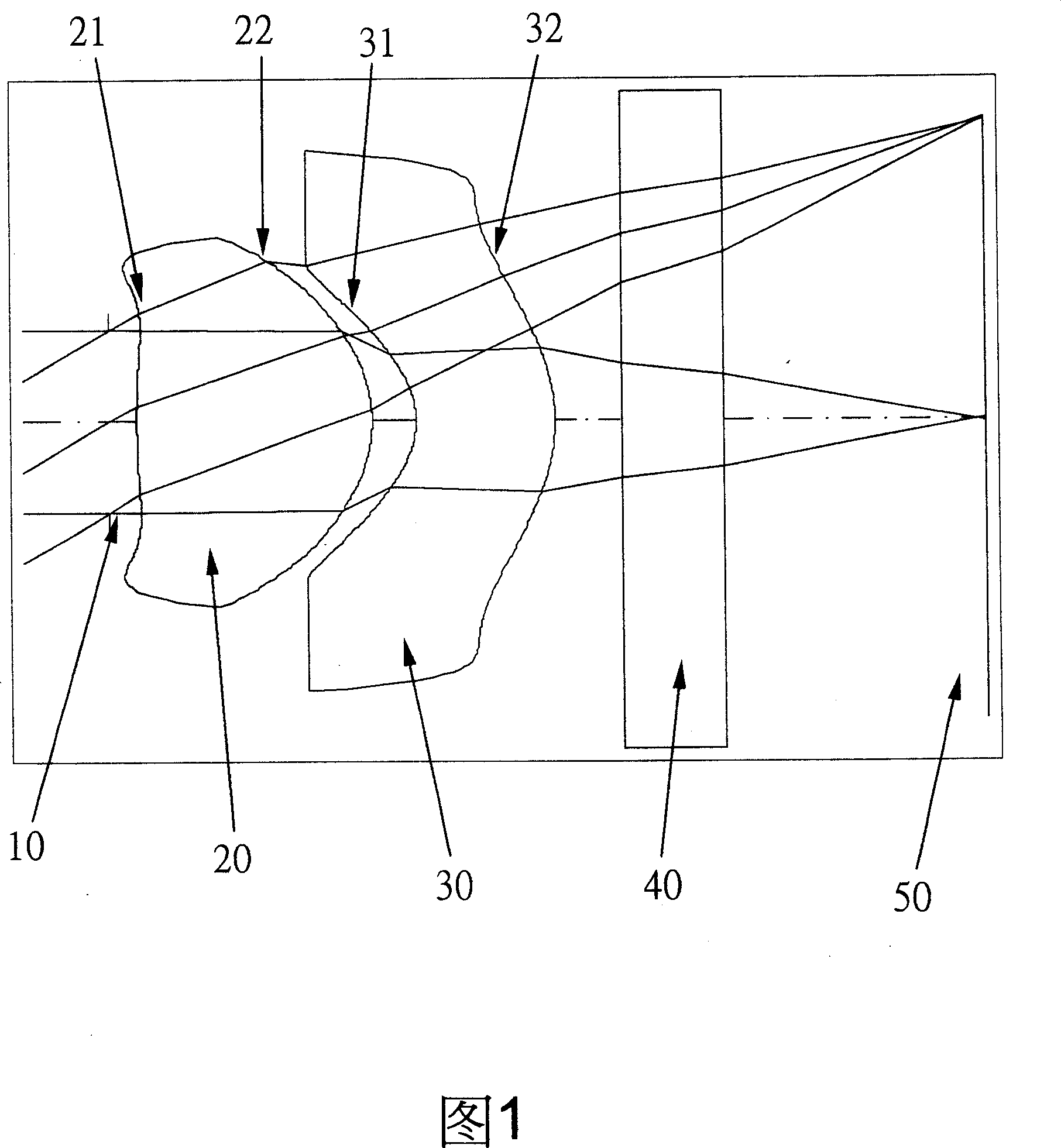
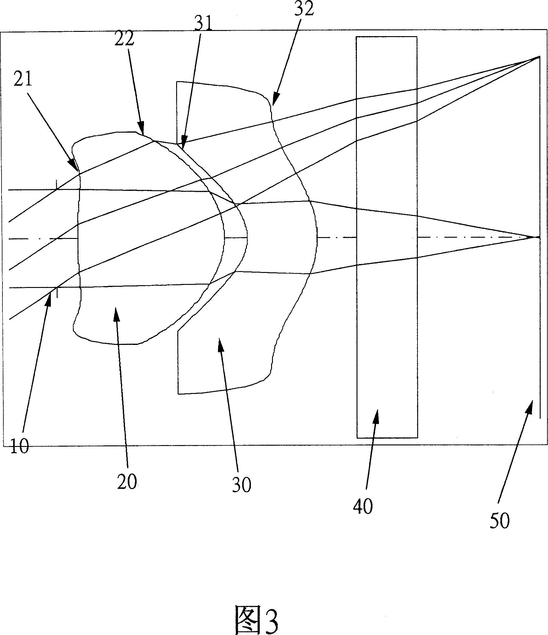
The invention discloses an imaging optical lens, consisting of two pieces of refracting plastic lenses. From object to image, firstly a first lens with positive refracting power is matched with convex front surface and back surface; the refractive index N1 meets the relation that and N1 is less than 1.6 and more than 1.5; the focal length is f1, the systematic focal length is f and both meets the relation that f / f1 is more than 2.0; the front and back surfaces are both non spherical. A second lens with negative refracting power is arranged behind the first lens with concave front service and convex back surface; the refractive index N2 is more than 1.55; the front and back surfaces are both non spherical. In an optical imaging system, an aperture is set and arranged in front of the first lens for controlling the brightness of the optical system. Due to the lens structure, arrangement and lens configuration, the invention can effectively reduce the volume of lens and further obtain high definition.
Description
technical field [0001] The invention relates to an optical mirror group, in particular to a miniaturized imaging optical mirror group applied to a camera phone. Background technique [0002] In recent years, with the rise of camera phones, the thickness of photographic lenses has gradually shrunk, and the photosensitive components of general digital cameras are nothing more than CMOS or CCD. Due to the advancement of semiconductor process technology, the pixel size of photosensitive components has changed from the early 7.4um has been reduced to the current 1.75um, which makes the demand for miniaturized photographic lenses more ardent. [0003] The current mobile phone lens, in order to consider the correction of aberration, mostly adopts three lens structures, the most common of which is the positive and negative triplet type. However, when the height of the lens is reduced from 5mm to 3mm, the volume of the imaging system is reduced, making the It becomes difficult to pl...
Claims
Login to View More Application Information
Patent Timeline
 IPC IPC(8): G02B9/10G02B1/04
Inventor汤相岐
OwnerLARGAN PRECISION