

Polarizing board adhibiting device
A polarizing plate and cladding technology, applied in optics, nonlinear optics, instruments, etc., can solve problems such as waste of space, slow operation speed, long moving route, etc., and achieve the effect of improving process efficiency
- Summary
- Abstract
- Description
- Claims
- Application Information
AI Technical Summary
Problems solved by technology
Method used
Image

Examples
Embodiment Construction
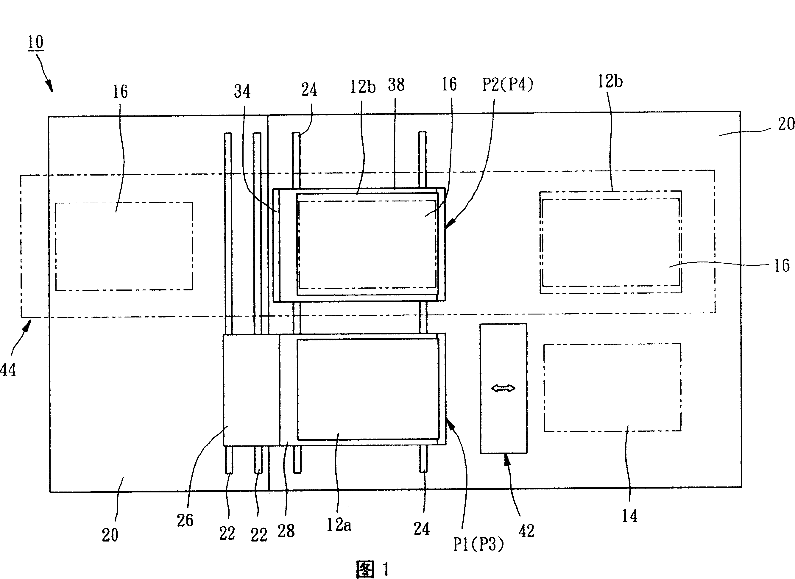
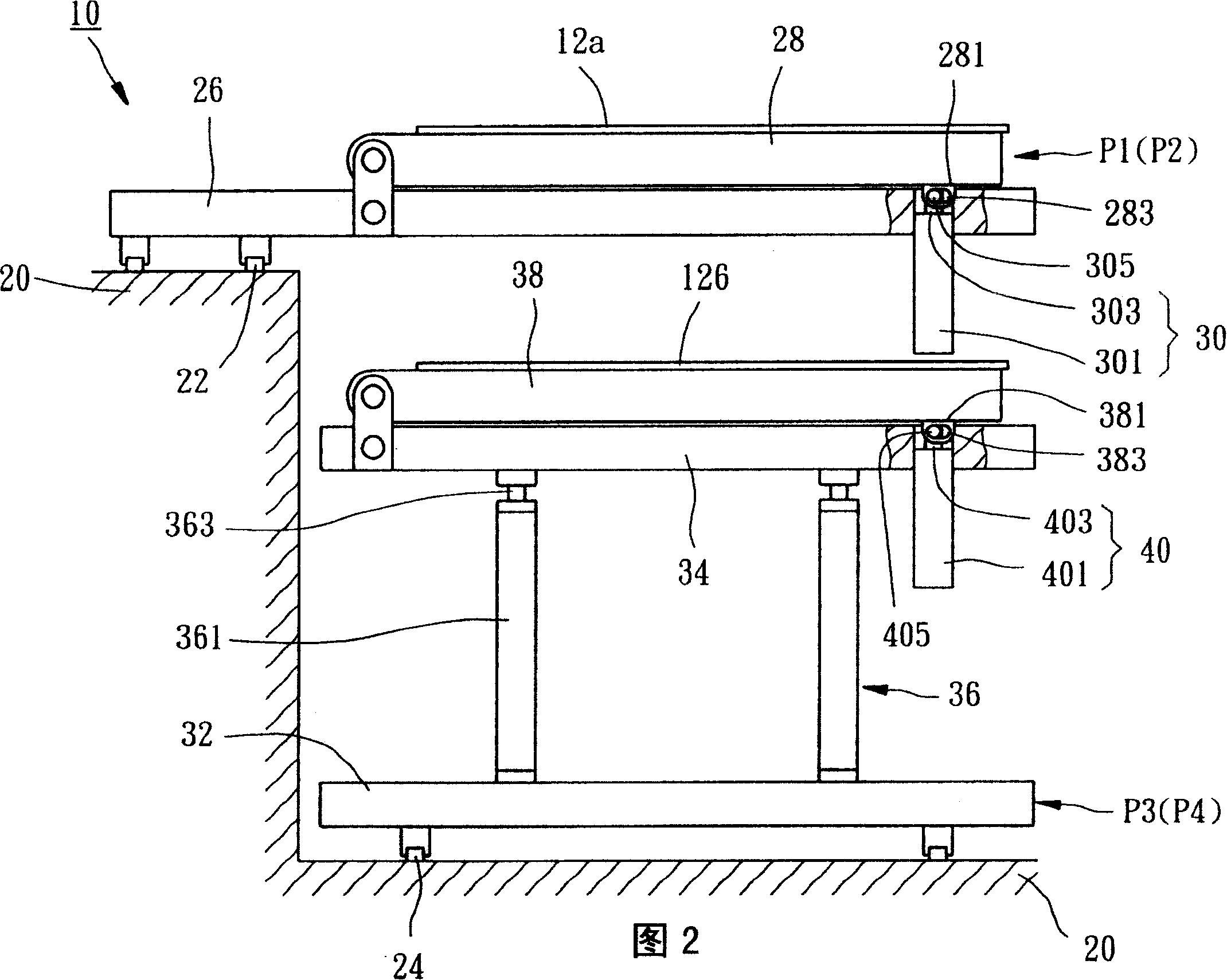
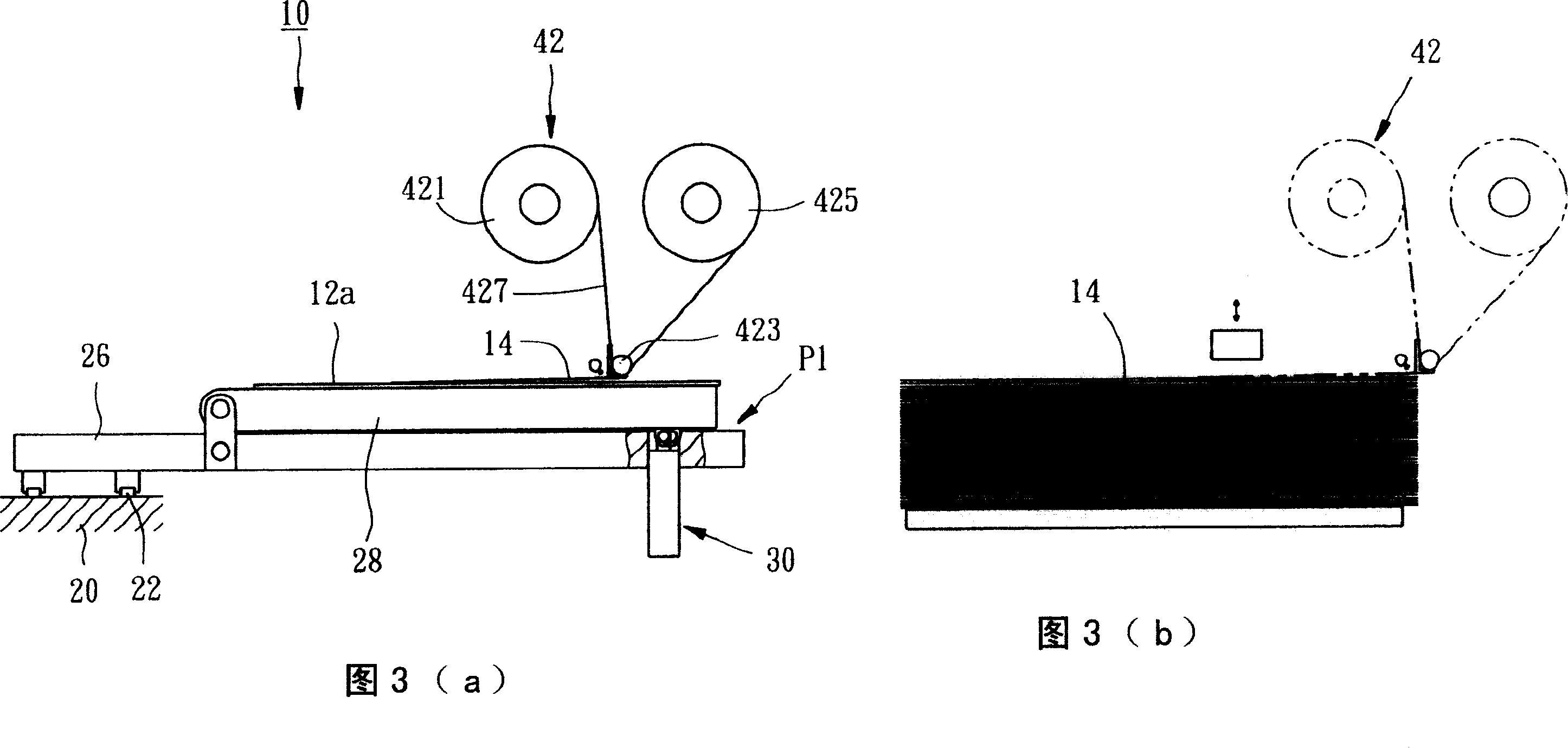
[0031] Please refer to Fig. 1, Fig. 2, the polarizer sticking device 10 that the preferred embodiment of the present invention provides is to tear off the protective film 14 on the polarizer 12a, 12b, and make this polarizer 12a, 12b and a The substrate 16 is combined together, and the substrate 16 is made of glass. The polarizer coating device 10 includes a base 20, two upper slide rails 22, two lower slide rails 24, an upper seat 26, an upper platform 28, A first power part 30 , a lower seat 32 , a lifting seat 34 , two second power parts 36 , a lower platform 38 , a third power part 40 , a film tearing device 42 and a conveyor 44 .
[0032] The upper sliding rail 22 and the lower sliding rail 24 are disposed on the base 20 parallel to each other.
[0033] The upper seat 26 is disposed on the upper slide rail 22 and can be driven to move along the upper slide rail 22 between a first position P1 and a second position P2.
[0034] One end of the upper platform 28 is pivotally...
PUM
 Abstract
Description
Claims
Application Information