Display device and its control method

A technology of display device and control method, applied in static indicators, instruments, etc., can solve problems such as inconvenience, general products have no structure, and increase the difficulty of load design.

Inactive Publication Date: 2008-02-13
GIGNO TECH CO LTD
View PDF0 Cites 3 Cited by
  • Summary
  • Abstract
  • Description
  • Claims
  • Application Information

AI Technical Summary

Problems solved by technology

[0006] Taking a liquid crystal display device at 56 o'clock as an example, and its resolution is 3840*2160, the scanning time allocated to each scanning line is ms. In other words, when the resolution is higher, the scanning time of each scanning line is The shorter the allocated scanning time, the higher the resolution, the faster the driving speed of the scanning line driving unit will increase its load and the difficulty of its design, which may even lead to misoperation of the liquid crystal display device
[0007] It can be seen that the resolution of the above-mentioned existing display devices obviously still has inconvenience and defects in structure and use, and needs to be further improved urgently.
In order to solve the above-mentioned problems, the relevant manufacturers have tried their best to find a solution, but no suitable design has been developed for a long time, and the general products do not have a suitable structure to solve the above-mentioned problems. This is obviously related. The problem that the industry is eager to solve

Method used


Image

  • Display device and its control method
  • Display device and its control method
  • Display device and its control method

Examples


Embodiment Construction

[0047] In order to further explain the technical means and effects of the present invention to achieve the intended purpose of the invention, the specific implementation, structure, features and methods of the display device and its control method proposed according to the present invention will be described below in conjunction with the accompanying drawings and preferred embodiments. Its effect is described in detail below.

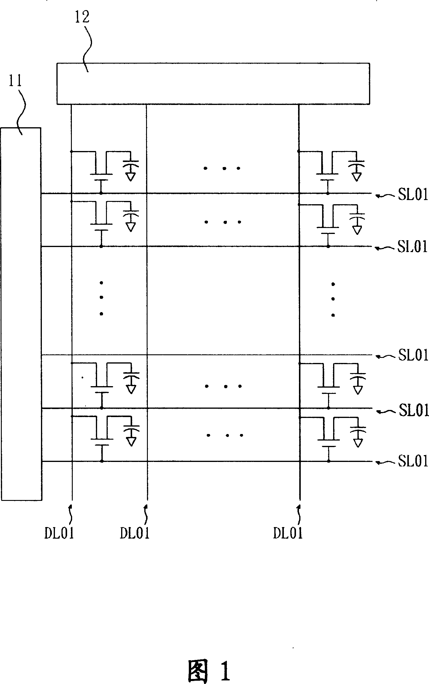
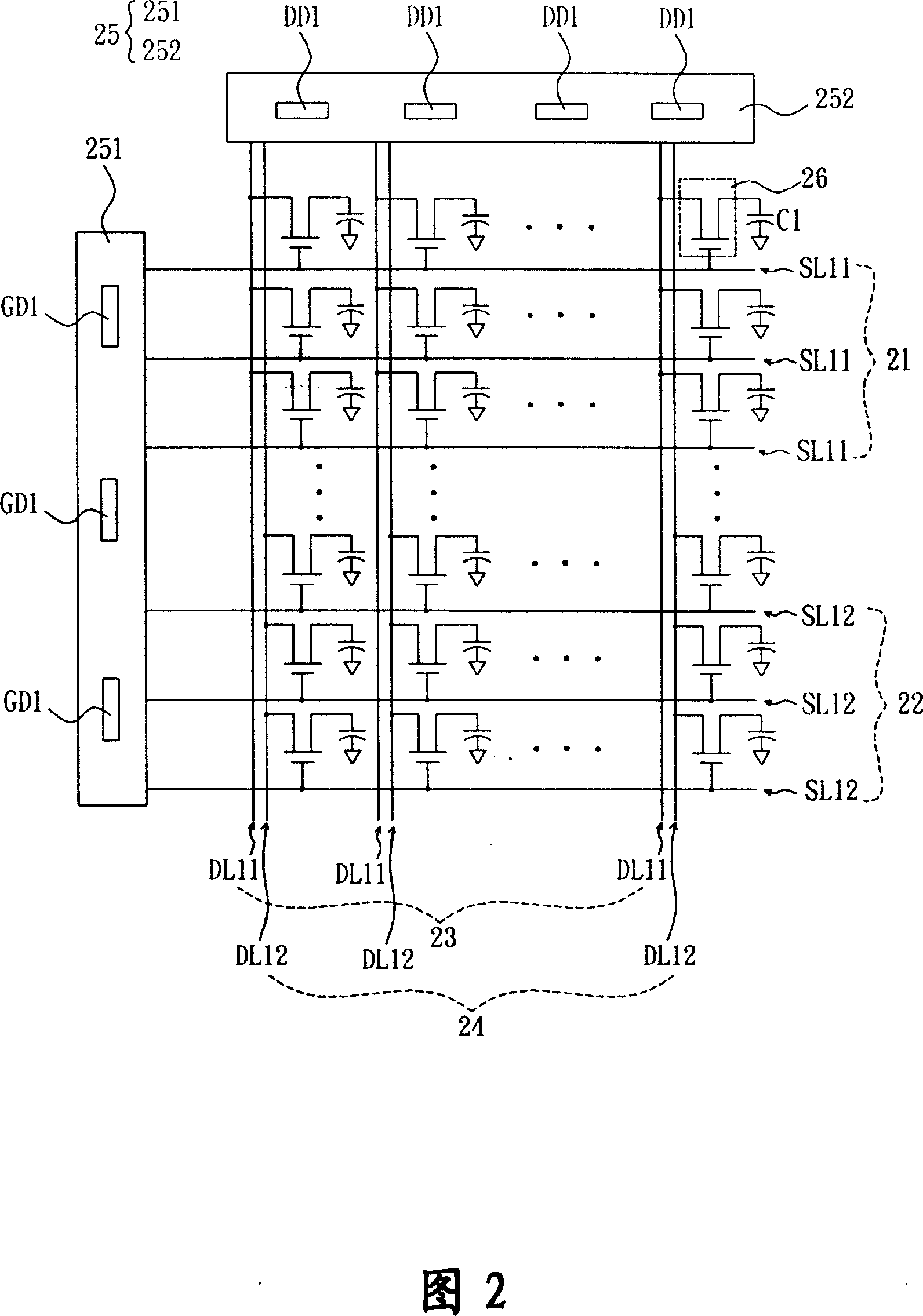
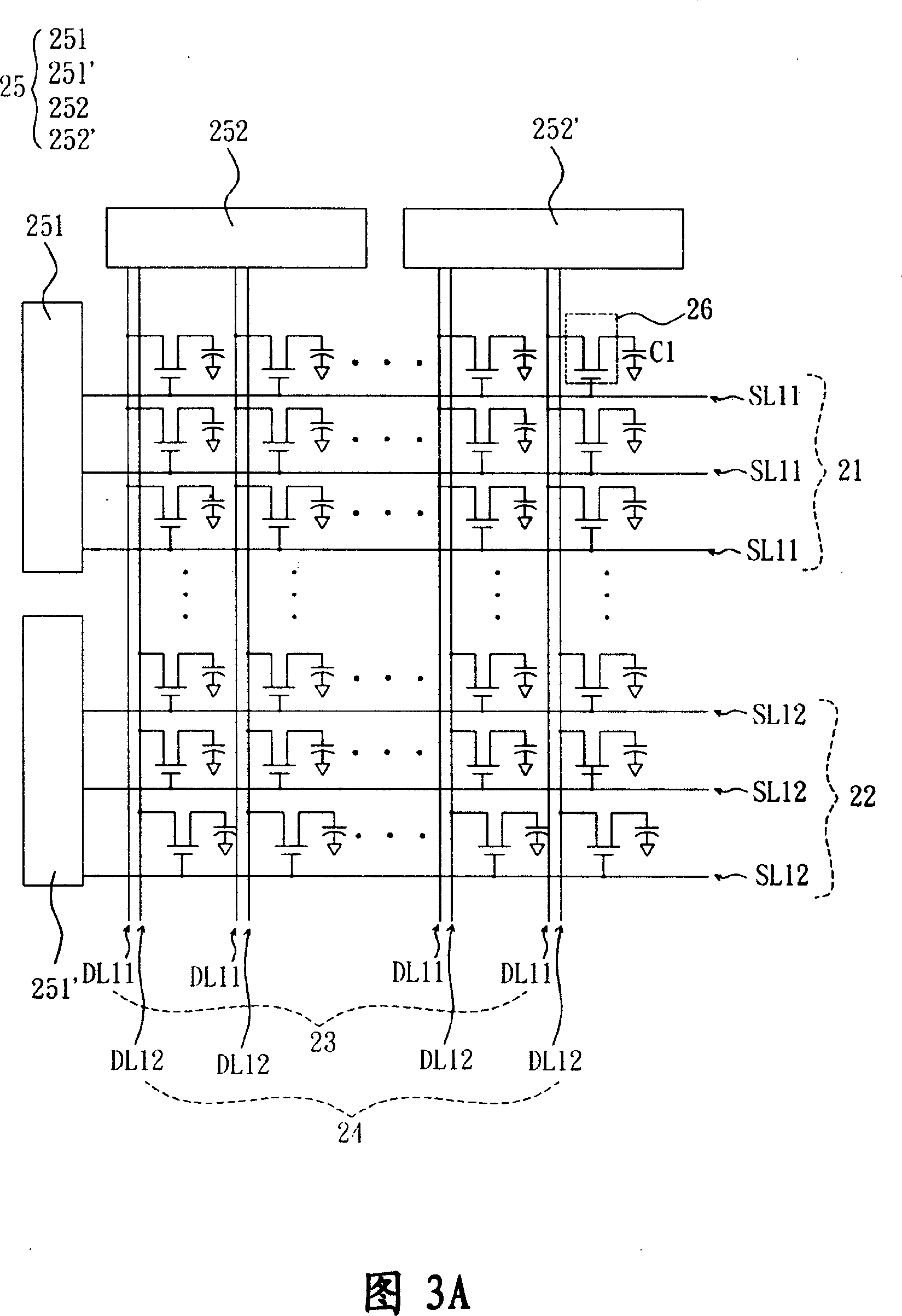
[0048] Please refer to FIG. 2, the display device of the preferred embodiment of the present invention includes a first scanning line group 21, a second scanning line group 22, a first data line group 23, a second data line group A group 24 and a driving unit 25 . Wherein, the display device can be a flat display device such as a liquid crystal display device, a plasma display device, or a digital light source processing (Digital Light Processing, DLP) projection device, a single crystal silicon liquid crystal (Liquid Crystal on Silicon, LCoS) projectio...


PUM


Abstract

The invention relates to a display device and the control method, and comprises a first scanning line group, a first data line group, a second scanning line group, a second data line group and a driving unit. The first scanning line group comprises an even number of first scanning lines; The first data line group comprises an even number of first data lines, which are separately electrically connected with the first scanning lines; the second scanning line group comprises an even number of second scanning lines; the second data line group comprises an even number of second data lines, which are separately power connected with the second scanning lines; and the driving unit is separately power connected with the first scanning line group, the first data line group, the second scanning line group and the second data line group, and is used for driving the groups. The purpose of the invention is lengthening scanning period of each scanning line of the display device, which makes the invention more practical.

Description

technical field [0001] The present invention relates to a display device and a control method thereof, in particular to a display device capable of being effectively used in a large size and a control method thereof (DISPLAY APPARATUS AND CONTROLMETHOD THEREOF). Background technique [0002] With the advancement of display technology, flat-plane display devices (Flat-plane Display) have gradually replaced traditional cathode ray tube displays (Cathode Ray Tube, CRT), and become the mainstream in the market. [0003] Recently, with the widespread use of flat-panel display devices and the improvement of technology, the size of the display panel has also increased accordingly. As the size of the display panel gradually increases, people's requirements for resolution also increase accordingly. [0004] Currently, the resolution of display devices has evolved from the early Extended Graphics Array (XGA) specification to the Wide Extended Graphics Array (WXGA) specification, and ...

Claims


Application Information

Patent Timeline
Patent Type & Authority Applications(China)
IPC IPC(8): G09G3/36G09G3/20G02F1/133
Inventor 林峰立
Owner GIGNO TECH CO LTD
Why Eureka
Try Eureka