
Method and device for self-cleaning and voltage-dependent electro static filtering

An electrostatic filtering and cleaning technology, applied in the direction of electrostatic separation, electrode cleaning, etc., can solve problems such as low efficiency

Active Publication Date: 2008-02-13
COMMISSARIAT A LENERGIE ATOMIQUE ET AUX ENERGIES ALTERNATIVES
View PDF0 Cites 3 Cited by
  • Summary
  • Abstract
  • Description
  • Claims
  • Application Information

AI Technical Summary

Problems solved by technology

[0006] Systems utilizing physical phenomena are generally less efficient, but produce neither pressure loss nor secondary waste

Method used


Image

  • Method and device for self-cleaning and voltage-dependent electro static filtering
  • Method and device for self-cleaning and voltage-dependent electro static filtering
  • Method and device for self-cleaning and voltage-dependent electro static filtering

Examples


Embodiment Construction

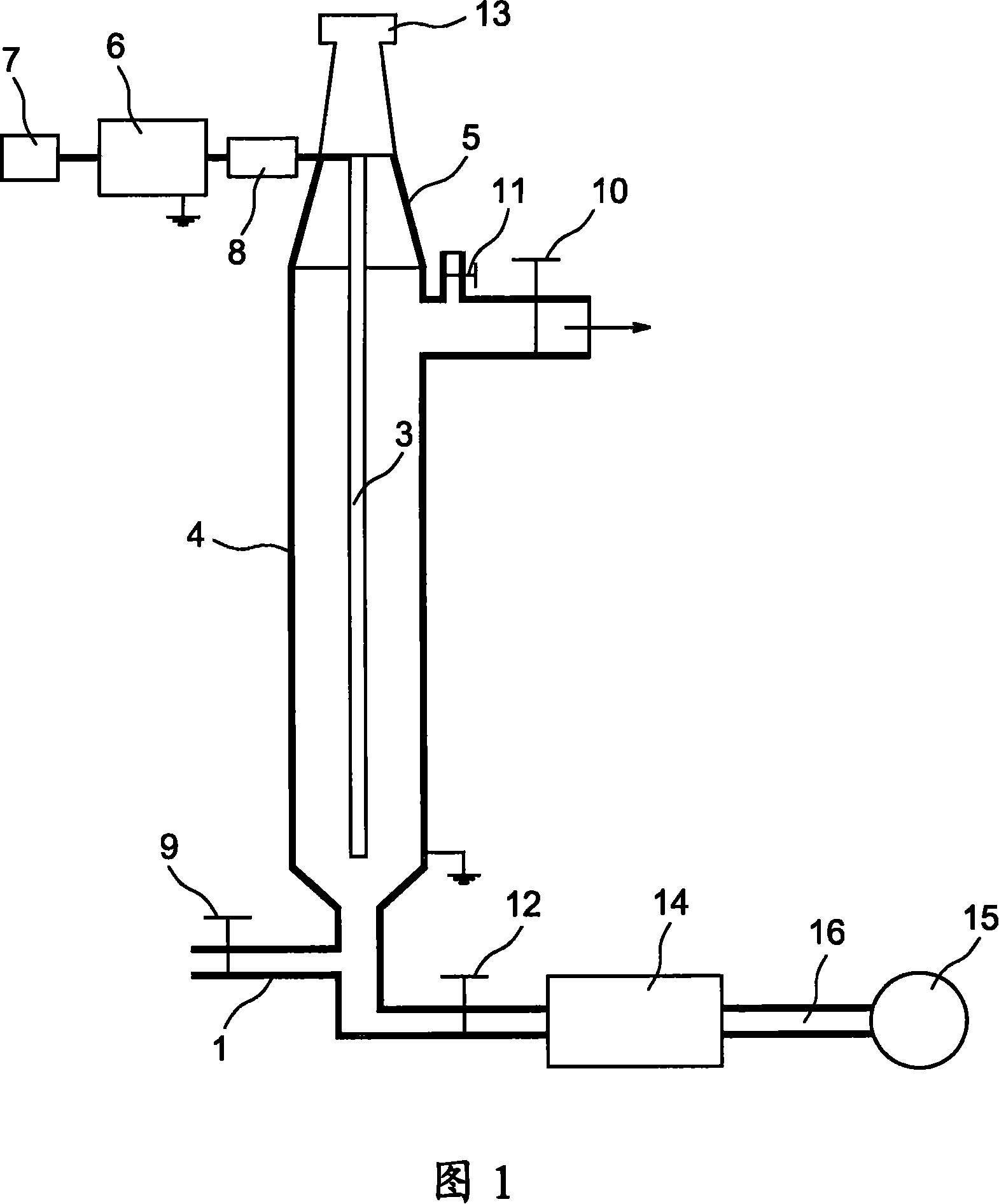
[0021] Referring to Fig. 1, the filtering method and apparatus according to the present invention repeats the standard pipe structure in which the dust-laden fluid is introduced through the inlet 1 arranged at the lower part of the pipe 4, the inner temperature of which is lower than 140°C. Inside the tube 4 there is a high voltage electrode 3 supported by an isolator 5, which occupies most of the length of the tube 4, forming a grounded counter-electrode. The fluid to be filtered is discharged from the outlet 2 arranged in the upper part of the pipe 4 . If the air flow is relatively high, the electrode 3 must be rigid and stably attached.

[0022] A high voltage generator 6 powers the electrodes 3 and is connected to control means 7 comprising a computer capable of detecting the arc generated between the high voltage electrodes 3 and the tube 4 . By means of the control device 7 it is possible to control the wave generator 13 (to be described later), for example with respect...


PUM


Abstract

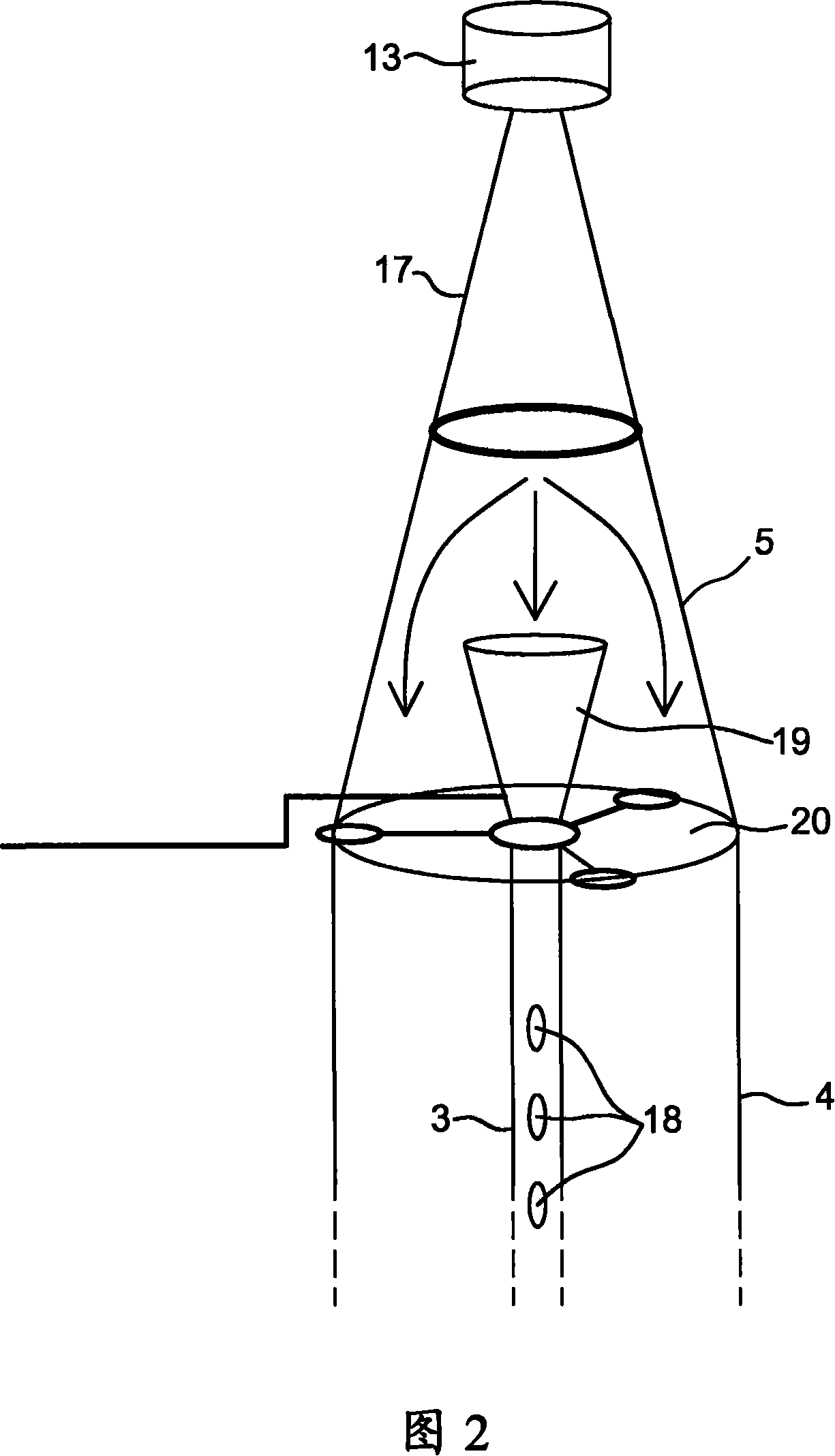
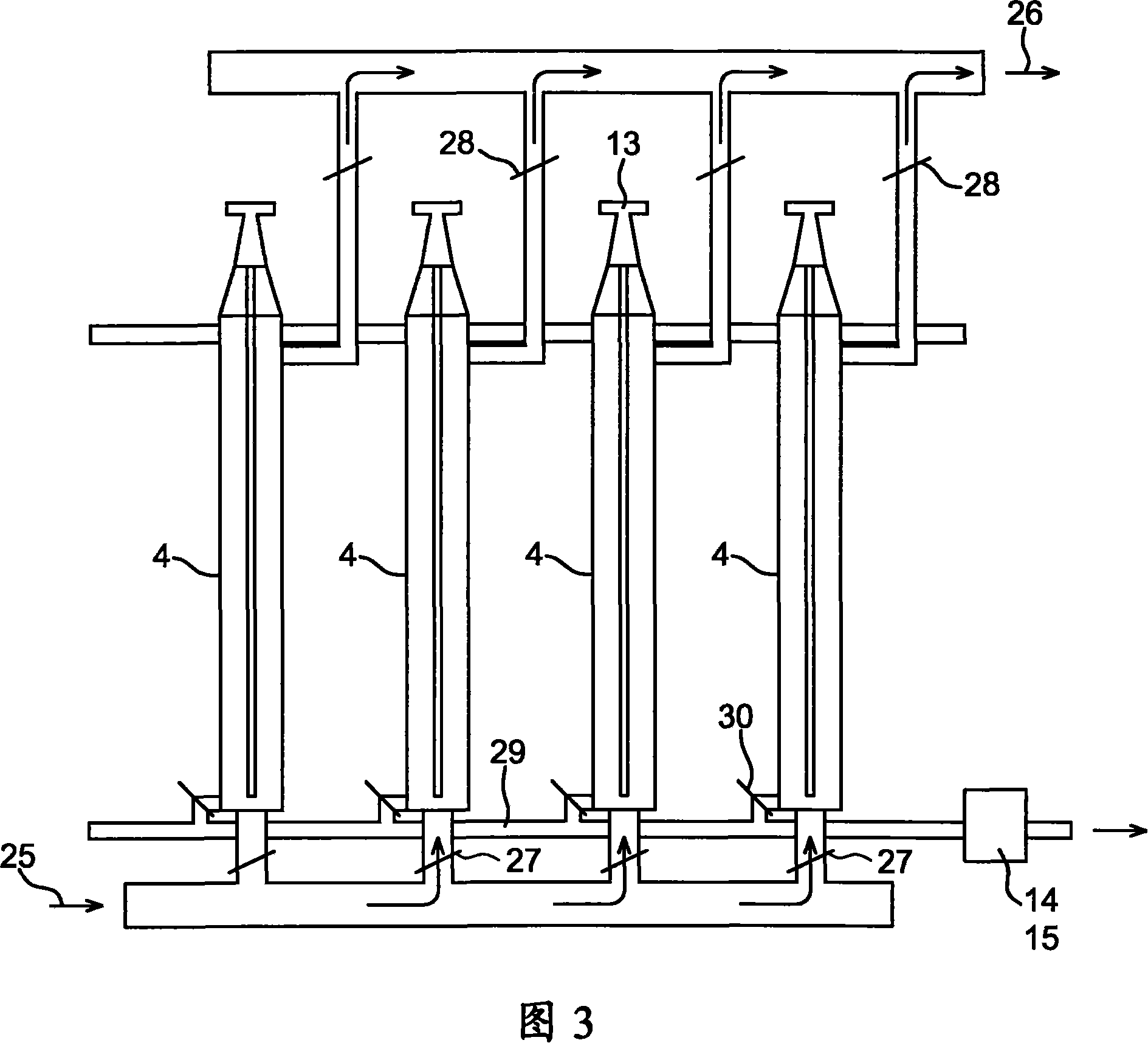
The invention concerns a system for cleaning electrolytic filtering installations without pressure drop or dismantling of the system. The filtering voltage is maintained at a maximum breakdown-limit value. It consists in equipping each assembly consisting of a tube (4) and a high-voltage electrode (3) with a sound generator (13) arranged at one end to operate it, when the filtering operation is stopped, so as to cause the dust to drop which can then be sucked up by a recovery system consisting of a recovery chamber (14) and an extractor (15). The invention is applicable to all installations involving toxic dust.

Description

technical field [0001] The present invention relates to the field of industrial installations (equipment) producing toxic dust (dust, dust) or non-dust such as particles (particles) suspended in a fluid. This case is a heat treatment method for hazardous substances such as organic nuclear waste, toxic industrial waste or hazardous raw materials. It also relates to the field of electromagnetic filter devices. Background technique [0002] In many of the aforementioned devices (apparatus) extremely efficient filtration systems are required in order to intervene in those devices dealing with fluids in which dust or particles are suspended. [0003] There are many filtration systems, which can be divided into the following three categories: systems using mechanical devices, systems using fluids, and systems using physical phenomena. [0004] The former employ effective physical and mechanical barriers, such as sleeve filters, bag filters, and particle bed filters, but pressure...

Claims


Application Information

Patent Timeline
Patent Type & Authority Applications(China)
IPC IPC(8): B03C3/76
CPCB03C3/76
Inventor 弗洛朗·勒莫尔让-克洛德·克奈博奥利维耶·洛朗斯特凡娜·邦塞尔
Owner COMMISSARIAT A LENERGIE ATOMIQUE ET AUX ENERGIES ALTERNATIVES
Learn More