A video error tolerance control system and method

A fault-tolerant control and video technology, applied in the field of video communication, can solve problems such as the reduction of video fluency

Active Publication Date: 2008-02-20
TENCENT TECH (SHENZHEN) CO LTD
View PDF1 Cites 17 Cited by
  • Summary
  • Abstract
  • Description
  • Claims
  • Application Information

AI Technical Summary

Problems solved by technology

[0005] The technical problem to be solved by the present invention is to provide a video fault-tolerant control system and method for the problem of perceivable video fluency reduction caused by data packet loss in video communication

Method used


Image

  • A video error tolerance control system and method
  • A video error tolerance control system and method
  • A video error tolerance control system and method

Examples


Embodiment Construction

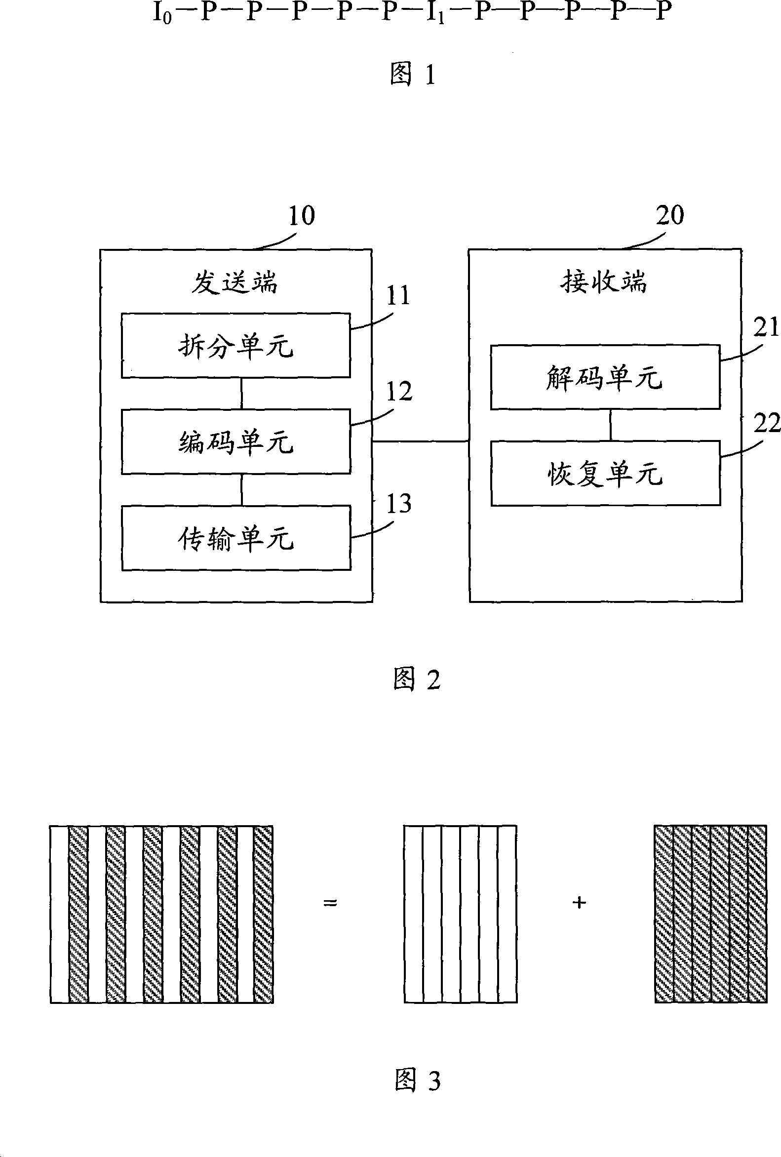
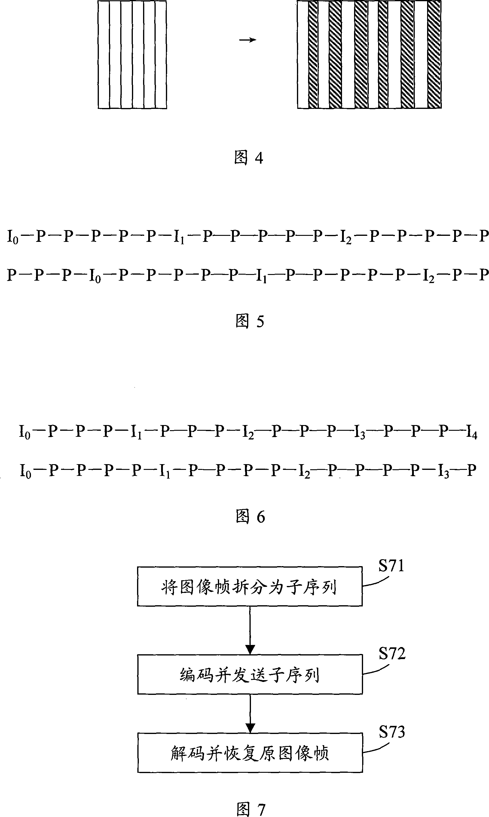
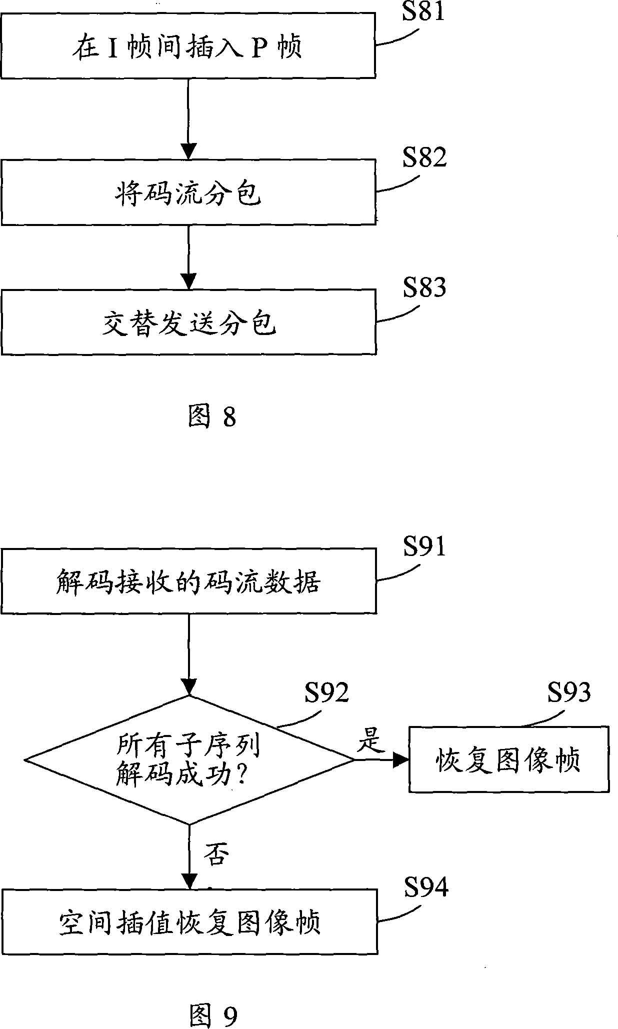
[0043] Aiming at the perceivable decrease in video fluency caused by data packet loss during video transmission, the present invention provides a fault-tolerant control system and method for improving video fluency. The present invention splits a single frame image of a video sequence into two or more subsequences at the sending end of video communication, and independently encodes each subsequence, and encodes the code stream of each subsequence received at the receiving end of video communication Decoding is performed, and when only part of the sub-sequence code stream of the received image is decodable, the original image is restored by performing spatial interpolation according to the decoded sub-sequence.

[0044] As shown in FIG. 2 , it is a schematic structural diagram of an embodiment of a video fault-tolerant control system of the present invention. The system includes a splitting unit 11, an encoding unit 12, a transmission unit 13, a decoding unit 21, and a restorat...


PUM


Abstract

The utility model discloses a video fault tolerant control system, comprising a splitting element and a coding element and a transmitting element which are arranged on a sender, and a decoding element and a recovery element at a receiving end; wherein the splitting element is used to split a complete image frame of a video sequence into at least two subsequences; the coding element is used to code each of the subsequences independently into a code stream; the transmitting element is used to transmit the code stream of the subsequences to the receiving end respectively; the decoding element is used to decode the code stream of the subsequences; the recovery element recovers the original image frame according to the original split spatial relationship when all the subsequences are successfully decoded or the recovery element recovers the original image frame according to spatial interpolation calculation when parts of the subsequences are successfully decoded. The utility model also provides a relative method. The utility model has the advantages that the fault tolerant ability and the packet-loss resisting ability of video transmission as well as video playing fluency can be remarkably increased.

Description

technical field [0001] The present invention relates to the field of video communication, and more specifically, to a video fault-tolerant control system and method. Background technique [0002] With the development of network applications, video communication via the network has been widely used in occasions such as instant messaging and chat rooms. In video communication, the image frames in the video sequence are usually coded into I frames and P frames for transmission, where I frames are intra-frame coded frames, which are independently decoded without relying on other frames, and the coded stream is relatively large; P frames are An inter-frame coded frame depends on its previous I frame or P frame to be decodable, because the P frame refers to the previous frame image, so the code stream is relatively small. In order to adapt to network transmission, the code stream of each frame needs to be divided into several smaller data packets according to the network bandwidt...

Claims


Application Information

Patent Timeline
Patent Type & Authority Applications(China)
IPC IPC(8): H04N7/64H04N19/89
Inventor 陈敬昌
Owner TENCENT TECH (SHENZHEN) CO LTD
Why Eureka
Try Eureka