A light emitting device including anti-reflection layer(s)

A light-emitting device and anti-reflection technology, which is applied in the direction of electric solid-state devices, electroluminescent light sources, instruments, etc., can solve problems such as the difficulty of preventing Newton's rings

Inactive Publication Date: 2008-02-27
CORNING INC
View PDF0 Cites 12 Cited by
  • Summary
  • Abstract
  • Description
  • Claims
  • Application Information

AI Technical Summary

Problems solved by technology

Preventing Newton rings becomes more difficult as air gap thickness decreases

Method used


Image

  • A light emitting device including anti-reflection layer(s)
  • A light emitting device including anti-reflection layer(s)
  • A light emitting device including anti-reflection layer(s)

Examples


example 1

[0061] Example 1 - Monolayer MgF 2 coating

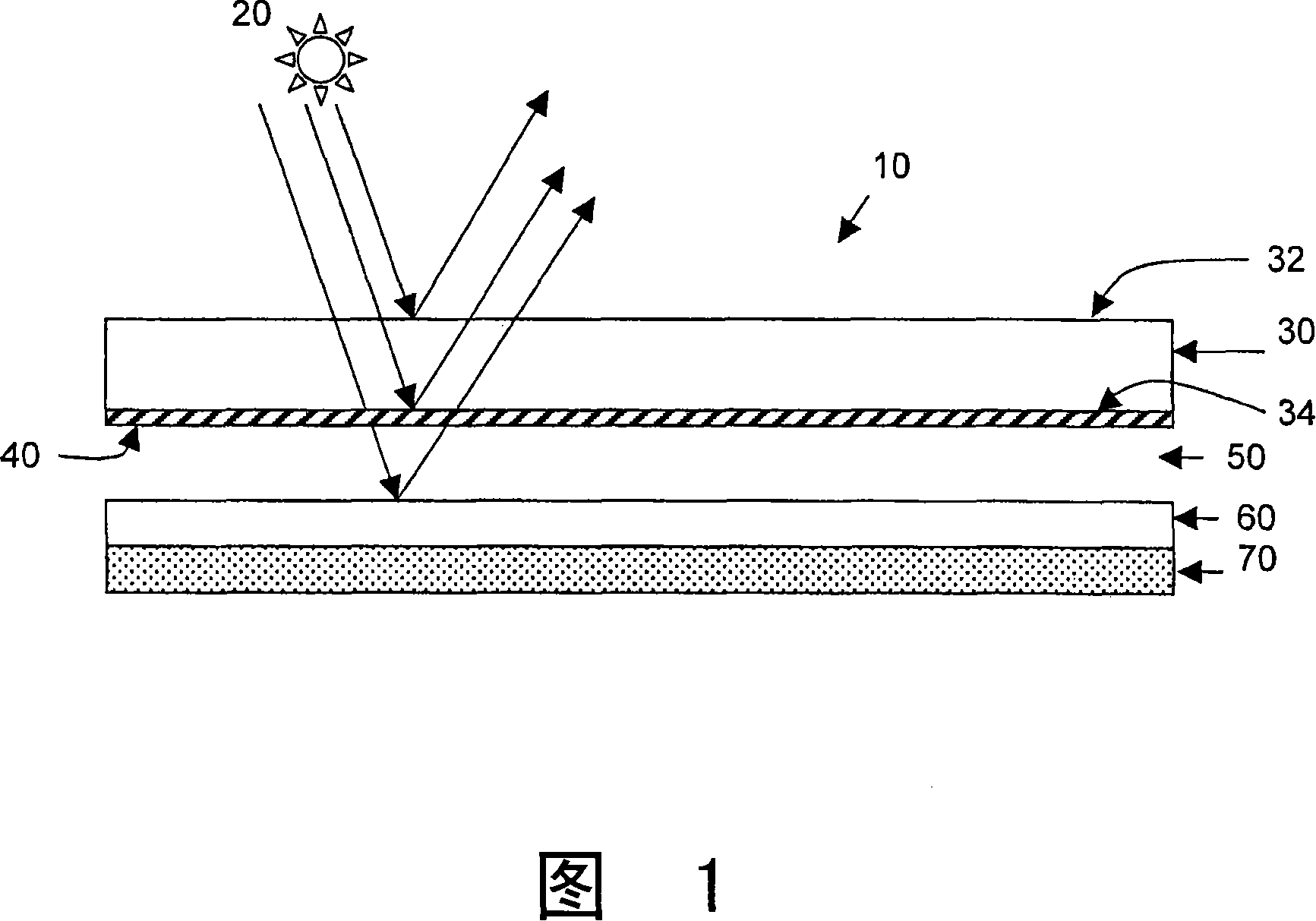
[0062] In the first example, a single layer of magnesium fluoride coating on a sheet of Eagle 2000TM One surface of the glass is modeled to simulate light-emitting devices covering the inner surface of the substrate. Eagle in this example 2000TM Glass has a refractive index of 1.507 at 589.3 nm, so based on the above theory, the target refractive index of the anti-reflection coating is 1.23 and an optical thickness of 147 nm. A single-layer magnesium fluoride coating has a refractive index of 1.38 and thus a physical thickness of approximately 107 nm.

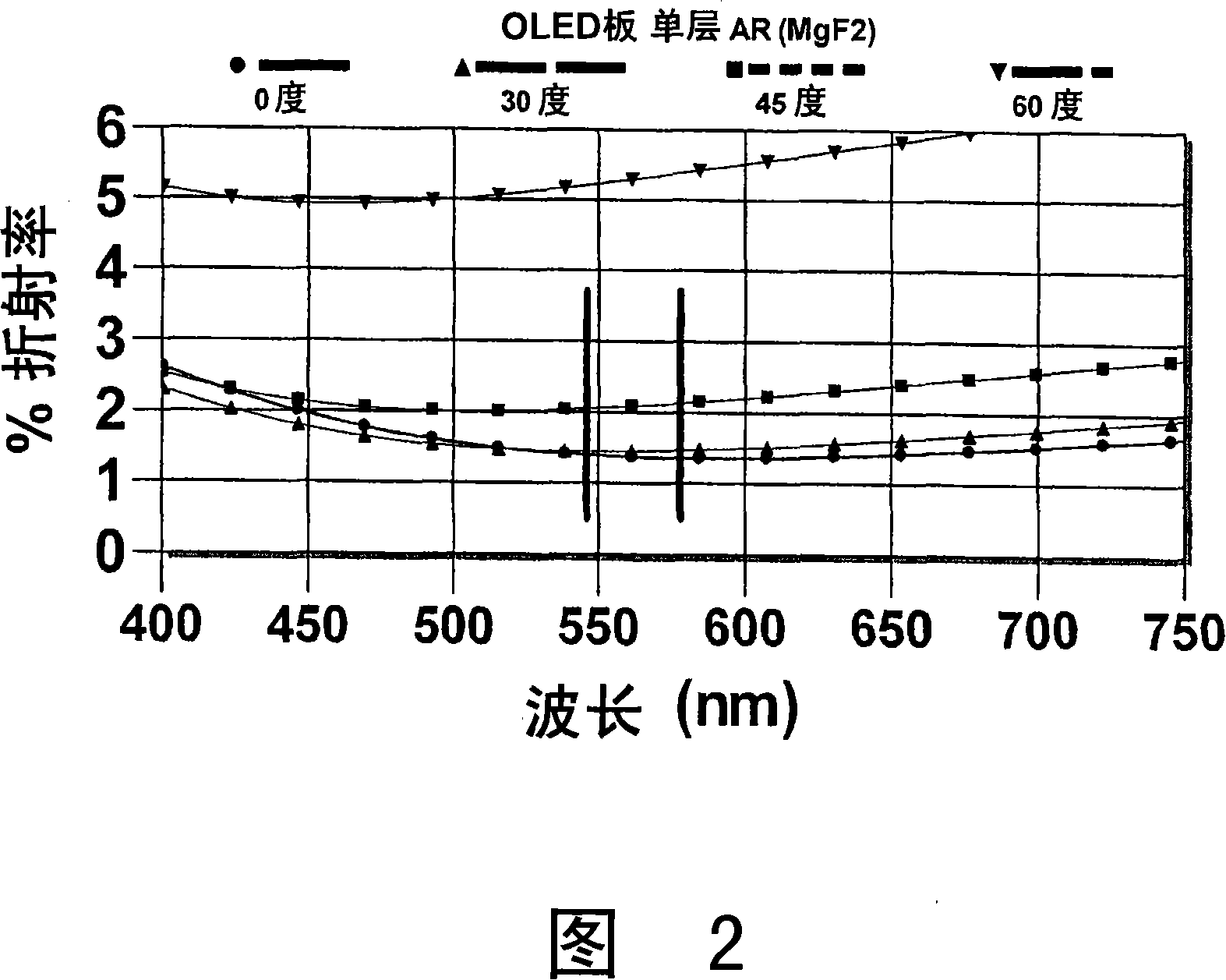
[0063] Figure 2 shows the modeled refractive index of a single-layer magnesium fluoride coating at different angles of incidence. At a wavelength of 546 nm, this refractive index is approximately 1.4% when viewed from an angle of incidence of 0 to 30 degrees. At a 45 degree incidence angle, the refractive index is slightly greater than two percent, and at a 60 degree incidence a...

example 3- 4

[0070] Example 3 - Four layers of anti-reflective coating

[0071] In the third example, four layers of anti-reflective coating on Eagle 2000TM Overlay the modeling on the substrate. The four-layer coating includes 12 nm of niobium oxide, about 36 nm of silicon dioxide, about 110 nm of niobium oxide, and a top layer of 90 nm of silicon dioxide.

[0072] As shown in Figure 7, the modeled reflectance for light at angles of incidence up to 45 degrees is less than one percent for visible wavelengths below 630 nm. The model indicated that the coating composition was sufficient to reduce the appearance of Newton's rings at angles of incidence up to about 45 degrees.


PUM

PropertyMeasurementUnit
thicknessaaaaaaaaaa
thicknessaaaaaaaaaa
thicknessaaaaaaaaaa

Abstract

A technique for reducing the appearance of Newton's Rings for a light emitting device is disclosed. The light emitting device comprises an anti-reflective coating on the inner surface of a cover substrate. A method of making a light emitting device is disclosed, together with a method for reducing the formation of Newton's Rings in a device.

Description

technical field [0001] The present invention relates to light emitting devices and methods of reducing Newton's rings, and more particularly to light emitting devices having anti-reflection (AR) coatings to reduce reflection of emitted light and / or ambient light without the use of circular polarizers. Background technique [0002] A newly developed class of flat-panel display technology uses organic light-emitting diodes (OLEDs) and thin light-transmitting electrode materials sandwiched between two thin glass plates. Since active light emitting materials are sensitive to damage by contaminants including water and oxygen, the perimeter of the device is usually sealed to maintain a water and oxygen free environment. Commercially available sealant systems generally do not provide a hermetic seal that will last for the life of the display, thus requiring a strong desiccant to be placed within the unit. The inclusion of a light-tight desiccant requires light emitted from the OLE...

Claims


Application Information

Patent Timeline
Patent Type & Authority Applications(China)
IPC IPC(8): H05B33/14H05B33/22H05B33/12G09F9/00
CPCH01L51/5281H10K59/8791H05B33/10G02B1/11H10K50/86
Inventor H·D·布克R·A·朗根斯芬R·L·梅尔
Owner CORNING INC
Why Eureka
Try Eureka