Super bright low reflectance liquid crystal display

a liquid crystal display and low reflectance technology, applied in the direction of identification means, instruments, polarising elements, etc., can solve the problem of not being able to easily read under high ambient light conditions, and achieve the effect of substantially improving the viewing characteristics of the liquid crystal display and substantially reducing the amount of back-reflected light seen by the viewer

Inactive Publication Date: 2006-01-05
VIA OPTRONICS GMBH
View PDF5 Cites 83 Cited by
  • Summary
  • Abstract
  • Description
  • Claims
  • Application Information

AI Technical Summary

Benefits of technology

[0014] The present invention is based, in part, on the innovative discovery that the amount of back-reflected light seen by a viewer of a liquid crystal display can be substantially reduced and, therefore, that the viewing characteristics of a liquid crystal display can be substantially improved by moving the front polarizer from its conventional location where it is adhered to the front surface of the liquid crystal display panel and is positioned rearwardly relative to the front cover plate to a new location where it is positioned in front of said front cover plate and is preferably adhered to the back surface of an additional cover plate itself positioned in front of said front cover plate.

Problems solved by technology

Unfortunately, however, one of the principal disadvantages of liquid crystal displays is that, due to their low contrast and a “washed-out” effect caused by back-reflected ambient light seen by a viewer, they cannot easily be read under high ambient light conditions, such as when placed in direct sunlight.

Method used


Image

  • Super bright low reflectance liquid crystal display
  • Super bright low reflectance liquid crystal display
  • Super bright low reflectance liquid crystal display

Examples


first embodiment

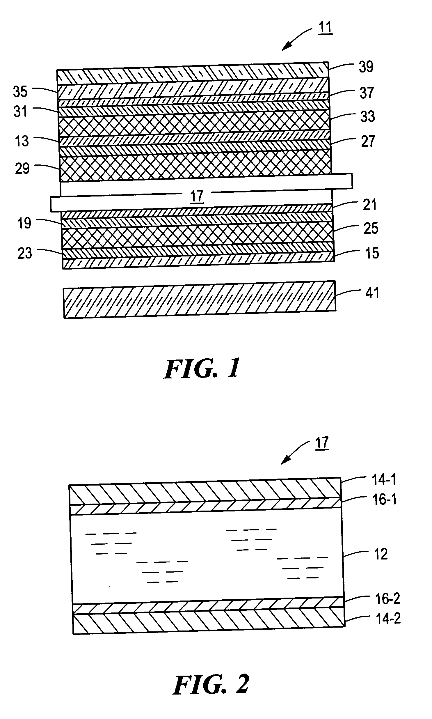
[0039] Referring now to FIG. 1, there is shown a schematic section view of a liquid crystal display constructed according to the teachings of the present invention, said liquid crystal display being represented generally by reference numeral 11.

[0040] Liquid crystal display 11, which is particularly well-suited for (but is not limited to) military applications, comprises a first glass substrate 13, a second glass substrate 15 and a liquid crystal display (LCD) panel 17, LCD panel 17 being positioned between glass substrates 13 and 15. Glass substrates 13 and 15, which may be conventional in nature and correspond to the front and rear cover plates of a conventional liquid crystal display, typically have a thickness of about 0.04 inch and may be made of a borosilicate, a sodalime or the like. Preferably, glass substrates 13 and 15 have indices of refraction that substantially match that of LCD panel 17. LCD panel 17, which is preferably (but not necessarily) an active matrix liquid cr...

second embodiment

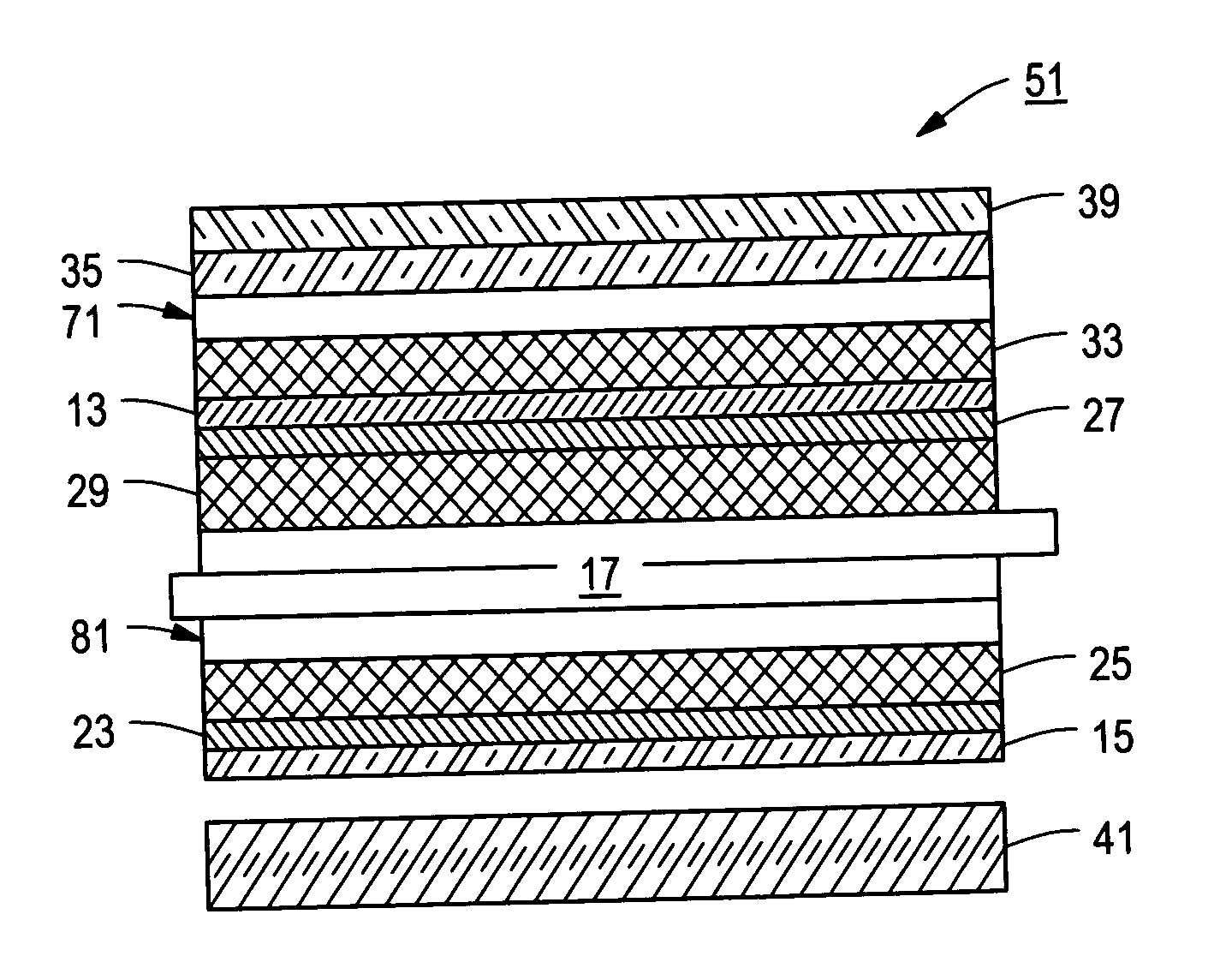
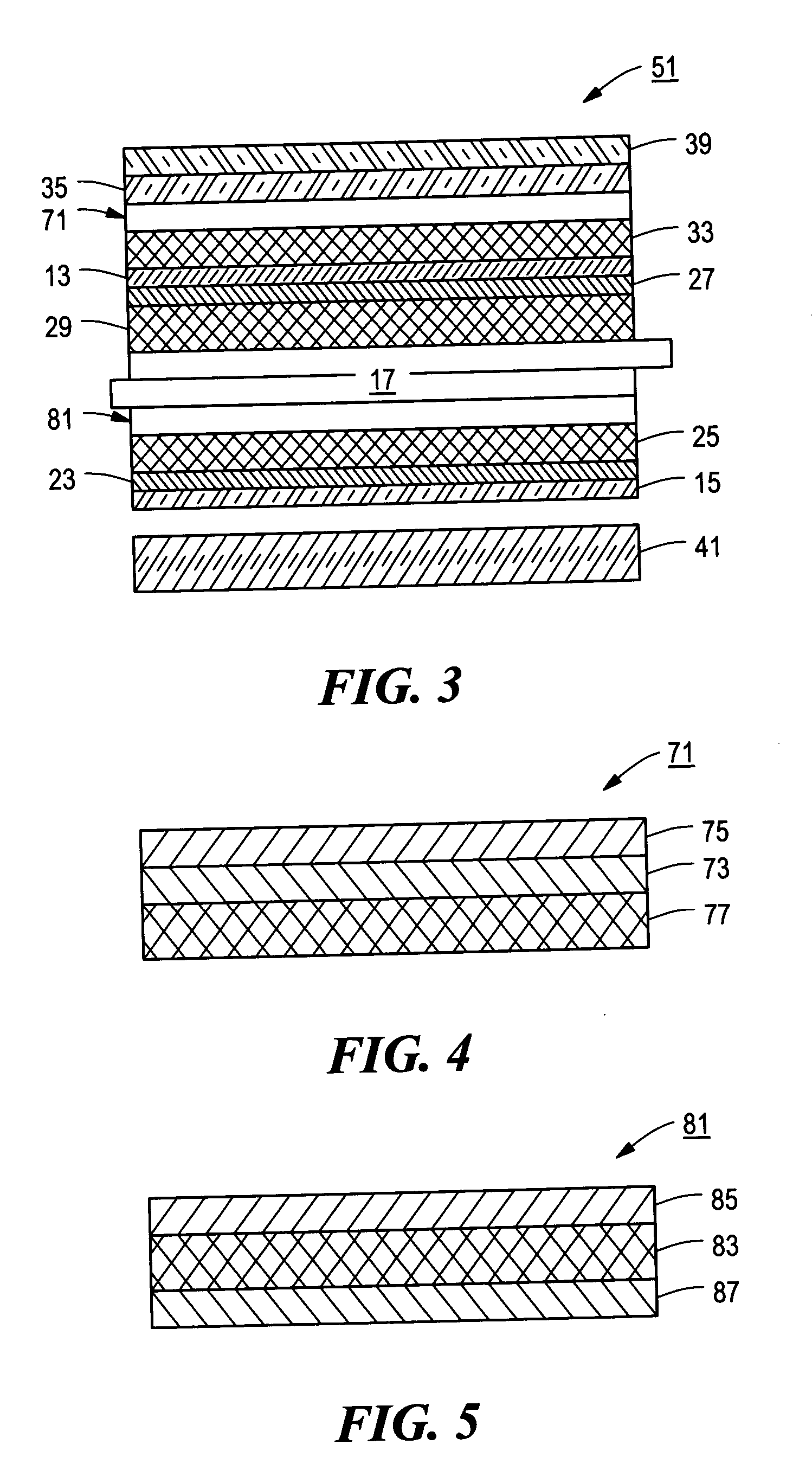
[0051] Referring now to FIG. 3, there is shown a schematic section view of a liquid crystal display constructed according to the teachings of the present invention, said liquid crystal display being represented generally by reference numeral 51.

[0052] Display 51, which is also particularly well-suited for (but not limited to) use in military applications, is similar in many respects to display 11, the principal differences between the two displays being that, in display 51, the combination of front polarizer 31 and adhesive 37 of display 11 are replaced with a polarizer assembly 71 and the combination of polarizer 19 and adhesive 21 of display 11 are replaced with a polarizer assembly 81.

[0053] Referring now to FIG. 4, polarizer assembly 71 is shown in greater detail. Polarizer assembly 71 comprises a neutral density polarizer 73, which may be conventional in nature. An index-matched, pressure sensitive adhesive 75, which may be conventional in nature, is applied to one side of pol...

third embodiment

[0058] Referring now to FIG. 6, there is shown a schematic section view of a liquid crystal display constructed according to the teachings of the present invention, said liquid crystal display being represented generally by reference numeral 101.

[0059] Display 101, which is particularly well-suited for non-military or commercial applications (e.g., cell phone screens, laptop monitors), comprises a liquid crystal display (LCD) panel 105, LCD panel 105 being identical to LCD panel 17 of display 11.

[0060] Display 101 also comprises a rear polarizer 109. The front surface of rear polarizer 109 is adhered to the rear surface of LCD panel 105 with an index-matched, pressure-sensitive adhesive 111. Polarizer 109 and adhesive 111 may be identical to polarizer 19 and adhesive 21, respectively, of device 11 and may be manufactured together in the form of a polarizer assembly.

[0061] Display 101 additionally comprises a front polarizer 115, front polarizer 115 being crossed relative to rear p...


PUM

PropertyMeasurementUnit
thicknessaaaaaaaaaa
thicknessaaaaaaaaaa
thickaaaaaaaaaa

Abstract

A liquid crystal display (LCD) exhibiting enhanced optical viewing performance. In a preferred embodiment, the LCD comprises a liquid crystal display panel, the liquid crystal display panel comprising a pair of transparent substrates, liquid crystal material sandwiched between the transparent substrates and transparent electrodes positioned between the liquid crystal material and the transparent substrates. The LCD also comprises a rear polarizer assembly comprising a compensation film, a polarizer mounted on the rear surface of the compensation film, and a first index-matched, pressure sensitive adhesive (PSA) mounted on the front surface of the compensation film, the PSA being adhered to the rear surface of the LCD panel. The LCD also comprises a front polarizer assembly, the front polarizer assembly comprising a front polarizer, a compensation film mounted on the rear surface of the front polarizer and an index-matched PSA mounted on the front surface of the front polarizer. The front polarizer is crossed relative to the rear polarizer. The front polarizer assembly may be adhered to the front of the LCD panel with a second index-matched, optical bonding material or may be spaced therefrom by an air gap. A transparent cover is mounted on the second index-matched PSA. The transparent cover is preferably a plastic plate. The plastic plate may be textured to reduce glare or may have an anti-reflection coating or an anti-reflection film applied to the front surface thereof. Instead of a plastic plate, the transparent cover may be a glass plate or a touch panel.

Description

CROSS-REFERENCE TO RELATED APPLICATIONS [0001] The present application is a continuation of U.S. patent application Ser. No. 09 / 772,197, inventors Sanelle et al., filed Jan. 29, 2001, which in turn is a continuation-in-part of U.S. patent application Ser. No. 09 / 235,584, inventors Sanelle et al., filed Jan. 22, 1999, now U.S. Pat. No. 6,181,394, the disclosures of which are incorporated herein by reference.BACKGROUND OF THE INVENTION [0002] The present invention relates generally to liquid crystal displays and more particularly to an improved liquid crystal display exhibiting enhanced optical viewing performance. [0003] Liquid crystal displays, which were first introduced in the 1970's and have since been used in watches, clocks, pocket calculators, portable personal computers, navigational instruments and the like, are electronically switched displays that make use of changes in the reflective properties of liquid crystals present in an electric field. A typical liquid crystal disp...

Claims


Application Information

Patent Timeline
Patent Type & Authority Applications(United States)
IPC IPC(8): G02F1/1335G02B5/30G02B1/11G02F1/13G02F1/133G02F1/1333G02F1/13363G09F9/00
CPCG02F1/1333G02F1/13338G02F1/133382G02F1/133502G02F1/133504G02F1/133528G02F2202/28G02F2001/133334G02F2001/13356G02F2001/133562G02F2001/133567G02F2201/38G02F1/13363G02F1/133334G02F1/13356G02F1/133562G02F1/133567
Inventor SANELLE, JOSEPH J.BREILING, DIGGY R.DOYLE, DANIEL R.
Owner VIA OPTRONICS GMBH
Why Eureka
Try Eureka