Workpiece clamping device of the numerical controlled solid carving machine
A technology of three-dimensional engraving machine and workpiece holder, which is applied in the field of engraving machines, can solve the problems of inability to process small handicrafts and small application range, and achieve the effect of increasing the application range, improving the qualified rate, and simple structure
- Summary
- Abstract
- Description
- Claims
- Application Information
AI Technical Summary
Problems solved by technology
Method used
Image
Examples
Embodiment 1
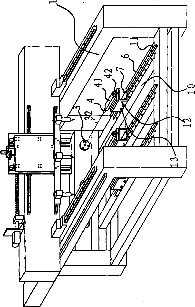
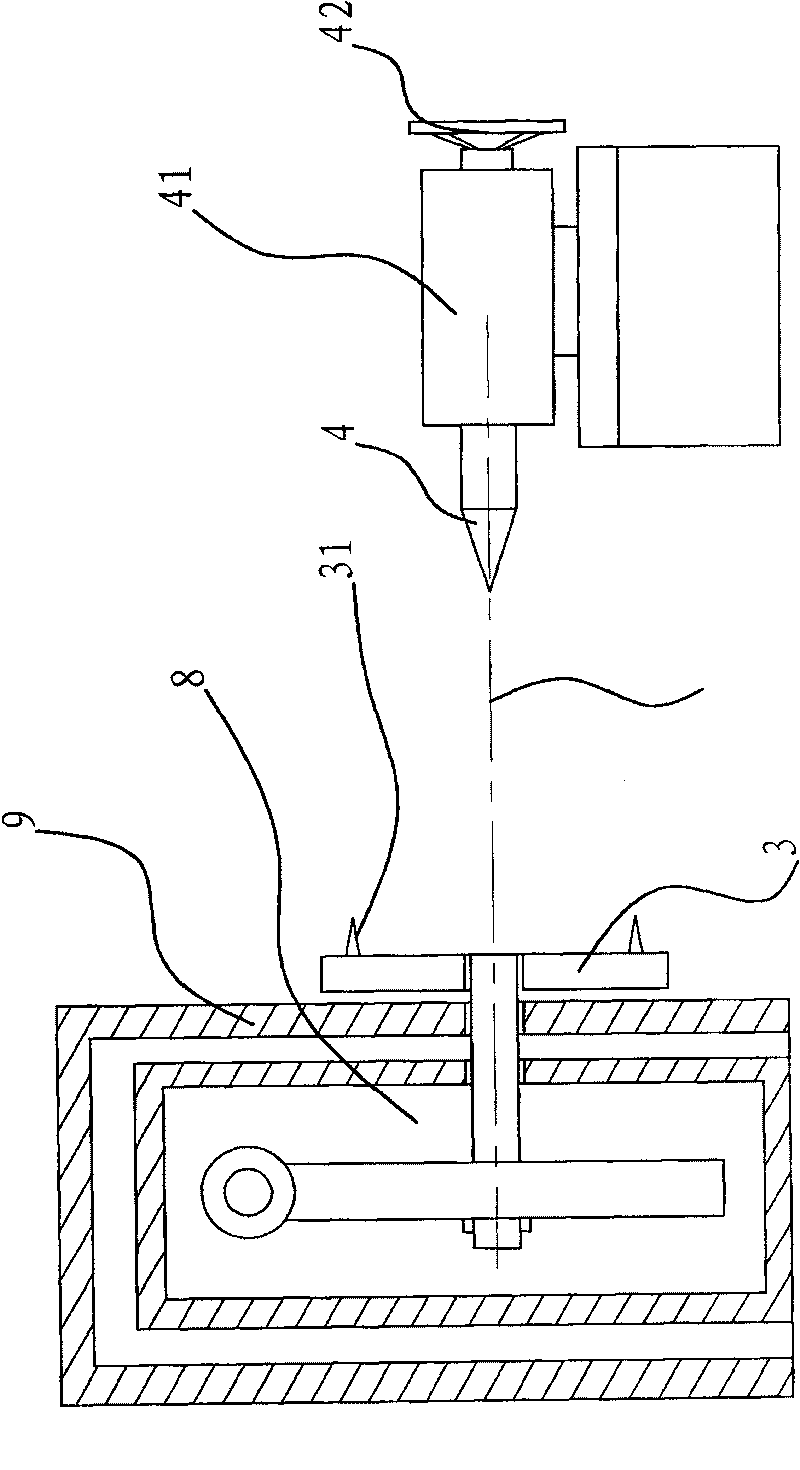
[0036] Such as figure 1 , image 3 and Figure 4As shown, the workpiece clamping device of the CNC three-dimensional engraving machine includes a frame 1, a motor 2, a turntable 3 and a top 4, and the frame 1 is provided with three turntables 3 installed side by side vertically, and the frame 1 in front of the turntable 3 There are tops 4 corresponding to the turntable 3 one by one. The tops 4 can expand and contract in the axial direction 32 of the turntable 3 and can work together with the turntable 3 to clamp the workpiece. The tops 4 face the center of the turntable 3 and are arranged A sliding mechanism capable of moving back and forth in the axial direction 32 of the turntable 3 is provided between the turntable 3 and the motor 2 with a rotating mechanism capable of rotating the turntable 3 .
[0037] Specifically, the tip 4 is arranged in the tip seat 41, and a handle 42 is provided on the tip seat 41, and a screw transmission mechanism is set between the tip 4 and th...
Embodiment 2
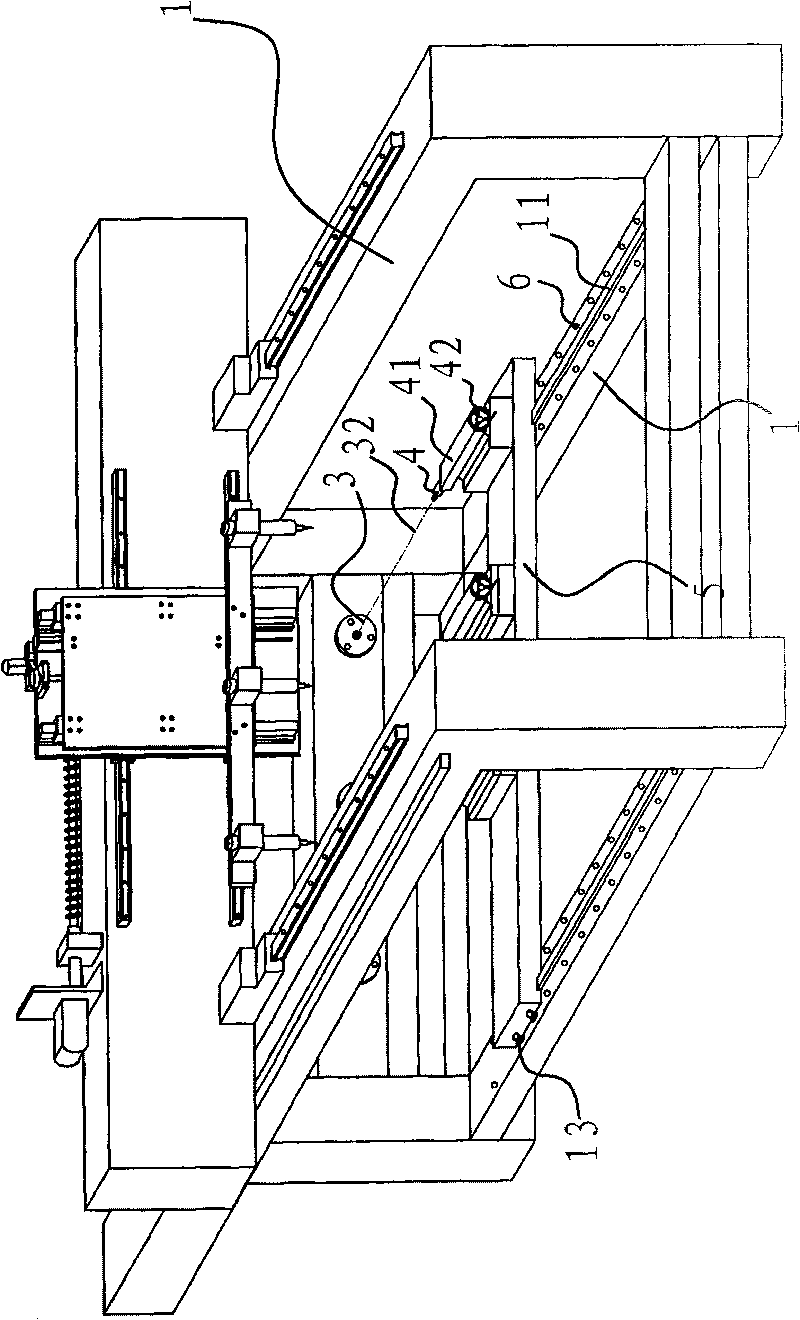
[0041] Such as figure 2 As shown, the content of Implementation 2 is basically the same as that of Embodiment 1. The difference is that the sliding mechanism in Embodiment 2 includes a crossbeam 5 that is arranged on the bottom of the frame 1 and can move back and forth along the axis direction 32 of the turntable 3. The two ends of the crossbeam 5 It is connected with the frame 1 where it is located by a guide rail 11 , the guide rail 11 is arranged along the axis direction 32 of the turntable 3 , and the top 4 is connected to the beam 5 . Specifically, a number of bolts 13 are provided on both sides of the end surface of the beam 5 , and the bolts 13 pass through the end surface of the beam 5 and abut against the guide rail 11 . In this way, the beam can be fixed on the frame 1 by bolts during processing. In order to further fix the crossbeam 5, a row of positioning holes 6 are respectively opened on both sides of the two guide rails 11 of the frame 1 where the two ends of...
Embodiment 3
[0043] Such as Figure 5 As shown, the content of embodiment 3 is basically the same as that of embodiment 1 or embodiment 2, the difference is that the number of motor 2 and turntable 3 is the same, and the motor 2 and turntable 3 are connected through a reducer, and the output shaft of each reducer It is fixedly connected with the turntable 3, and the input shaft of each reducer is connected with the rotating shaft of the motor 2, and each motor 2 is controlled by the control circuit to start and stop simultaneously. The control circuit realizes that multiple motors start at the same time, so that the turntable rotates synchronously at the same time.
PUM
 Abstract
Description
Claims
Application Information
 - R&D
- Intellectual Property
- Life Sciences
- Materials
- Tech Scout
- Unparalleled Data Quality
- Higher Quality Content
- 60% Fewer Hallucinations
Browse by: Latest US Patents, China's latest patents, Technical Efficacy Thesaurus, Application Domain, Technology Topic, Popular Technical Reports.
© 2025 PatSnap. All rights reserved.Legal|Privacy policy|Modern Slavery Act Transparency Statement|Sitemap|About US| Contact US: help@patsnap.com


