
Blade wheel structure and centrifugal fan device using the same

A technology of centrifugal fan and blade structure, which is applied to components of pumping devices for elastic fluids, non-variable pumps, machines/engines, etc., and can solve problems such as high difficulty, complex structure, and difficult processing

Inactive Publication Date: 2008-03-05
IND TECH RES INST
View PDF1 Cites 18 Cited by
  • Summary
  • Abstract
  • Description
  • Claims
  • Application Information

AI Technical Summary

Problems solved by technology

However, its structure is complex, processing is not easy, and the difficulty of design and analysis is also very high.

Method used


Image

  • Blade wheel structure and centrifugal fan device using the same
  • Blade wheel structure and centrifugal fan device using the same
  • Blade wheel structure and centrifugal fan device using the same

Examples


Embodiment Construction

[0020] In order to have a further understanding and understanding of the features, purposes and functions of the present invention, the following will describe the relevant detailed structure and design concept of the present invention, so as to understand the characteristics of the present invention, and the detailed description is as follows.

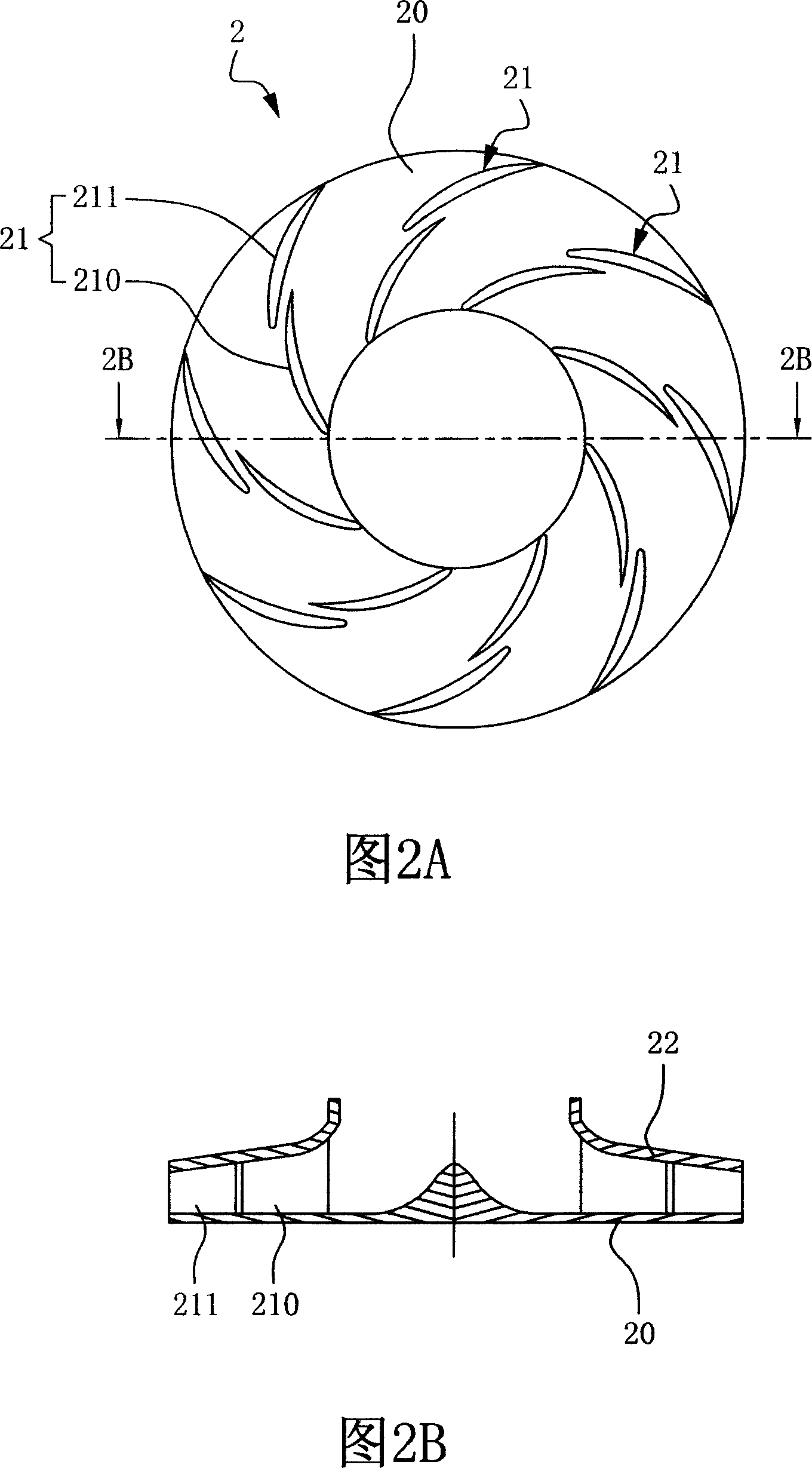
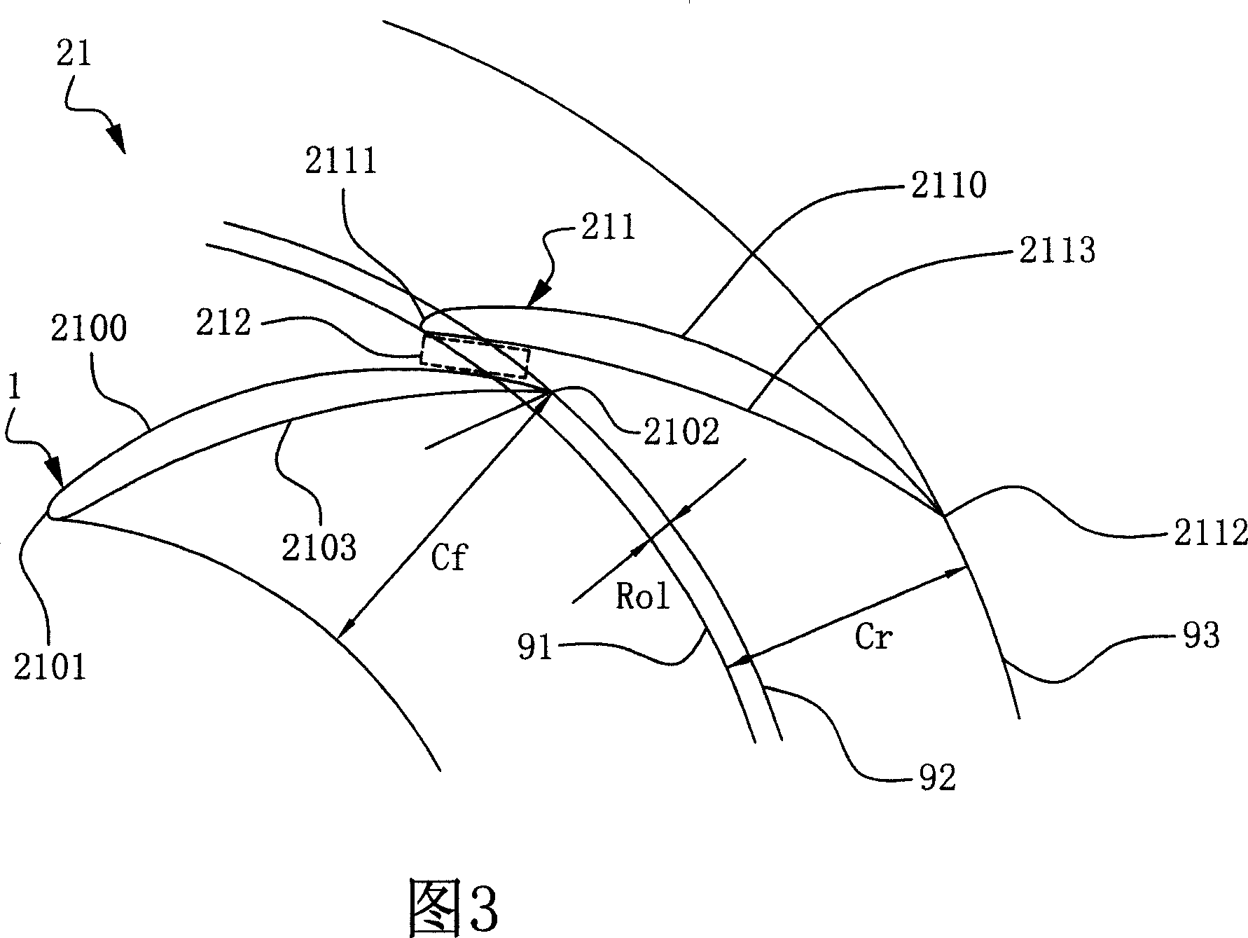
[0021] Please refer to FIG. 2A and FIG. 2B , which are top and cross-sectional schematic diagrams of a preferred embodiment of the impeller structure of the present invention. The impeller structure 2 includes: a disc body 20 ; and multiple pairs of blade structures 21 . The plurality of pairs of blade structures 21 are arranged on the disc body 20, and a front cover 22 is used to connect the plurality of blade structures 21. The blade structure 21 further includes: a first blade 210 and a second blade 210. Blade 211. The second vane 211 is disposed on one side of the first vane 210 , the second vane 211 and the first vane 210 have a...


PUM


Abstract

The impeller comprises a disk and multiple pairs of blades which are set on the disk and comprises a first blade and a second blade. The second blade is set on one side of the first blade. The first blade and the second blade have an overlapped region each other in radial direction. The overlapped region can form a gap passage acting a function like nozzle. When fluid sprays out from the gap passage, it can interrupt the grow-up of the boundary layer of the suction face of front column blade, and the high kinetic energy fluid mixes with the low kinetic energy fluid on the suction face of back column blade so as to reduce the boundary layer thickness, delay separation point position or overcome separation occurrence.

Description

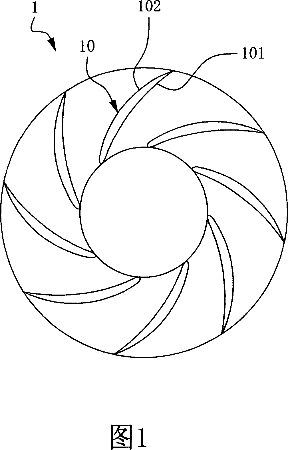
technical field [0001] The present invention relates to an impeller structure, in particular to an impeller structure in which two rows of blades overlap a little in the radial dimension to form a gap flow passage similar to a nozzle function, and a centrifugal fan device using the impeller structure. Background technique [0002] The centrifugal impeller is the heart of the centrifugal fan (fan), which plays a key role in product efficiency and noise level. The blade types of general centrifugal fan impellers can be divided into three types: backward-curved type, radial type and forward-curved type. Among them, the efficiency and noise of the backward-curved impeller Best performance. Then the inclined impeller blades are divided into plate and airfoil, and the airfoil blade has the highest efficiency and the lowest noise value. [0003] However, the structure of the conventional airfoil blades is a single row, please refer to FIG. 1 , which is a schematic top view of an ...

Claims


Application Information

Patent Timeline
IPC IPC(8): F04D29/30F04D29/66F04D29/68
Inventor 陈景富吴东权罗展兴强忠萍钟裕亮孙彦硕
Owner IND TECH RES INST
Learn More