Active wheel speed sensor tester

A technology of wheel speed sensor and tester, which is applied in the testing/calibration of brakes, speed/acceleration/shock measurement equipment, electronic circuit testing, etc., and can solve the problems that sensors cannot be easily tested

Inactive Publication Date: 2008-03-05
FORD GLOBAL TECH LLC
View PDF1 Cites 8 Cited by
  • Summary
  • Abstract
  • Description
  • Claims
  • Application Information

AI Technical Summary

Problems solved by technology

In particular, the tester cannot be easily used to test sensors in a variety of different cars, as different car models may have different harness connectors, and sensors and / or harnesses may assume different polarities
Also, the above device is not configured to identify problems associated with the ABS circuit or wiring, which would produce an error message that the sensor has failed

Method used


Image

  • Active wheel speed sensor tester
  • Active wheel speed sensor tester
  • Active wheel speed sensor tester

Examples


Embodiment Construction

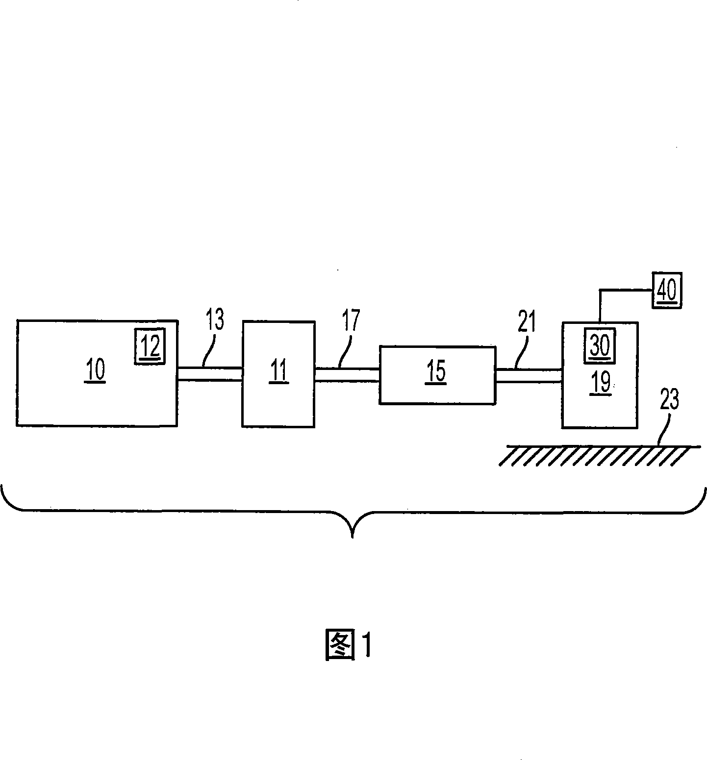
[0017] Active wheel speed sensors can be implemented with integrated circuits and magnets. The integrated circuit may contain a magnetic field responsive component, such as a Hall Effect sensor, that detects changes in the magnetic field passing through the sensing device. Active wheel speed sensors may be located near a rotating toothed tone wheel connected to the axle. As the teeth of the tonewheel pass near the wheel speed sensor, the magnetic field of the magnet distorts. Magnetic field responsive components detect changes in the magnetic field. As a result, the current in the sensor changes. In some embodiments, a sensor may have "low" and "high" states defined by current flow. Electronic control modules in automobiles, such as the anti-lock braking system electronic control module, can monitor the current level in the sensor circuit. Each transition from high to low may involve the passing of a gear tooth, and thus can be used to derive wheel or vehicle speed.

[00...


PUM


Abstract

A tester for testing an active wheel speed sensor of a vehicle, comprising: a module testing portion to assess operation of a system control module by monitoring an electrical output from the system control module and to indicate proper operation of the system control module with a first indicator; and a sensor testing portion to assess the operation of the active wheel speed sensor and to indicate proper operation with a second indicator.

Description

technical field [0001] The present invention relates to testing active wheel speed sensors. Background technique [0002] Active wheel speed sensors can be used to determine the rotational speed of the wheels and provide this information to vehicle control modules such as the anti-lock braking system (ABS). Occasionally, a wheel speed sensor needs to be tested to determine if it is functioning properly. Several types of active wheel speed sensors were previously tested when they were connected to the automotive wiring harness through a breakout box. The process can be cumbersome and time-consuming. [0003] A sensor testing method is described in US patent application 2005 / 0262921. The disclosed tester is used for in-situ testing of active wheel speed sensors and includes a window comparator component that generates a voltage output representing pass-fail criteria for the active sensor. The output of the comparator is connected to several LEDs. The lighting of the LED i...

Claims


Application Information

Patent Timeline
Patent Type & Authority Applications(China)
IPC IPC(8): G01P21/02G01R31/02G01R19/165G01P3/42G01P3/50
CPCB60T8/885B60T2270/406G01R31/2829G01P21/02G01R31/006G01R31/28
Inventor 克里斯托弗·贝尔
Owner FORD GLOBAL TECH LLC
Why Eureka
Try Eureka