Eureka AIR delivers breakthrough ideas for toughest innovation challenges, trusted by R&D personnel around the world.

Tyre bead structure

A technology of bead and bead wire, which is applied in the direction of tires, tire edges, tire parts, etc., can solve problems such as difficulties in manufacturing tires, and achieve the effect of good mechanical retention

Inactive Publication Date: 2008-03-05
MICHELIN & CO CIE GEN DES ESTAB MICHELIN
View PDF0 Cites 13 Cited by
  • Summary
  • Abstract
  • Description
  • Claims
  • Application Information

AI Technical Summary

Problems solved by technology

This bending strength can cause difficulties in tire manufacture, especially when the carcass reinforcement must be secured to the bead wire to form the bead

Method used


Image

  • Tyre bead structure
  • Tyre bead structure
  • Tyre bead structure

Examples


Embodiment Construction

[0037] In the description of the drawings, in order to make it easier to understand, similar elements will be denoted by the same reference numerals regardless of their structures or their functions.

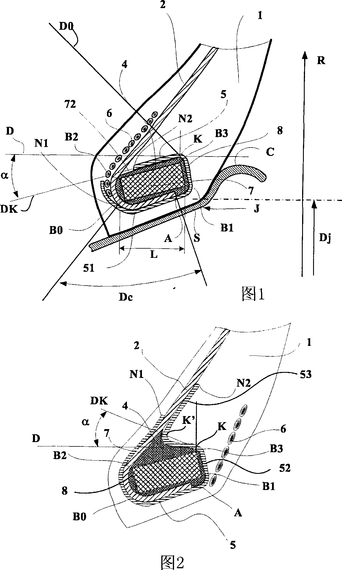
[0038]Figure 1 shows a tire bead 1 according to a first embodiment of the invention. Each bead 1 of this 315 / 60 R 22.5 tire comprises a reinforcement in the form of a metal bead wire 7 formed of a plurality of thin wires wound circumferentially, said bead wire being essentially of Four rectangular sections with vertices B0, B1, B2 and B3 defining four sides. Points B0 and B1 are located on the radially inward side of the cross-section of the bead wire, while points B2 and B3 are located on the radially outward side. Vertex B0 is the radially innermost point (ie, closest to the axis of rotation), and point B3 is the radially outermost point. In this example, the bead wire 7 has an axial width L equal to 20 mm, measured between the points B1 and B2 of the bottom axially furthest...


PUM


Abstract

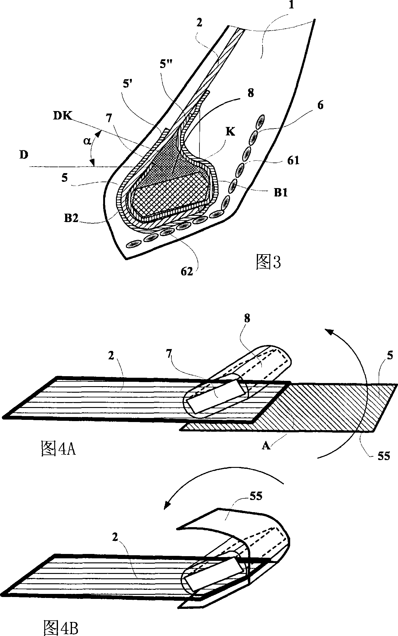
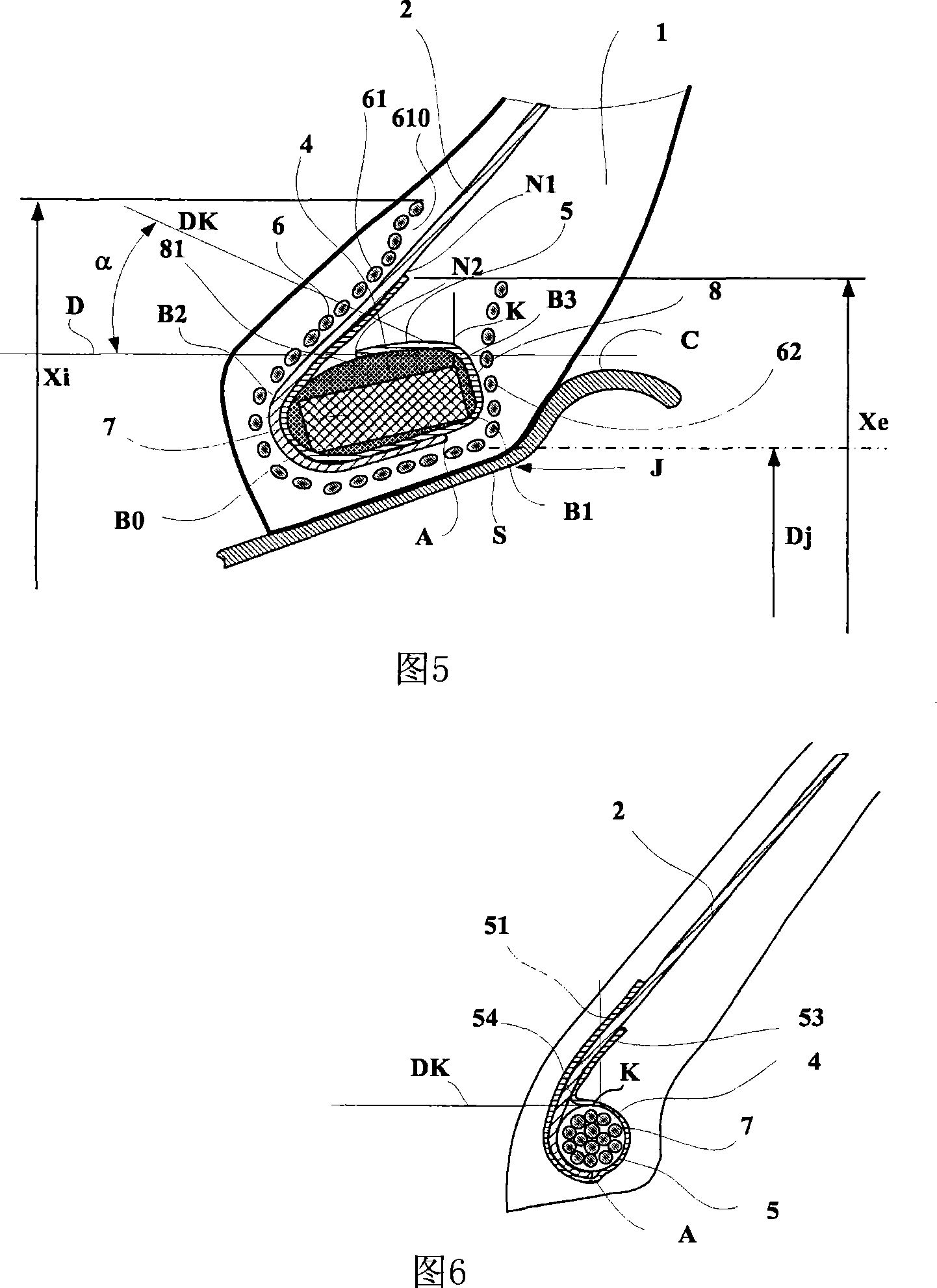
The invention relates to a tyre comprising sidewalls connecting a crown portion with beads (1) which are intended to come into contact with a mounting rim (J), said sidewalls comprising a carcass reinforcement (2) which is anchored in each bead (1) to at least one bead core (7) and which has one end (A) in each bead. Viewed in meridian cross-section, the bead core (7) has an external profile comprising two profile parts, namely: a first radially-inner part with axial width L which extends between the axially innermost point (B2) and the axially outermost point (B1), and a second radially-outer part between points B1 and B2. Each bead comprises at least one additional coupling reinforcement (5) which is in contact with the carcass reinforcement (2). The tyre is characterised in that, in each bead viewed in meridian cross-section, (i) the carcass reinforcement (2) is partially wound around the bead core (7) and is such that the end (A) thereof is positioned axially between the end points (B1 and B2) of the radially inner profile part of the bead core (7) and (ii) the additional coupling reinforcement (5) adjoins the carcass reinforcement (2) such as to be wound at least partially around the bead core (7), i.e. such as to cover at least partially the radially outer profile part of said core.

Description

technical field [0001] The present invention relates to a tire for load-carrying vehicles, and more particularly to the reinforcing structure of such a tire. Background technique [0002] As is known, a tire comprises a tread on top of a crown portion exhibiting circumferential and transverse strength, which is partly on top of a carcass reinforcement. The carcass reinforcement comprises a plurality of metallic reinforcing elements arranged radially, ie at an angle of at least 80° to the circumferential direction in the tire. Furthermore, the tire comprises beads intended to come into contact with the rim seat, these beads comprising at least one circumferential reinforcing member (such as a bead wire). One method of connecting the carcass reinforcement to the bead wire is to at least partially wrap said reinforcement around the bead wire, forming a bead extending to a certain height in the sidewall. This method of joining can, under conditions of use, lead to peeling betw...

Claims


Application Information

Patent Timeline
Patent Type & Authority Applications(China)
IPC IPC(8): B60C15/00B60C15/06
CPCB60C15/0018B60C15/0027B60C15/06B29D30/32Y10T152/10819Y10T152/10828Y10T152/10837
Inventor O·费兰B·格里森
Owner MICHELIN & CO CIE GEN DES ESTAB MICHELIN
Why Eureka
Eureka Blog
Learn More