
Sinus tarsi implant

a technology of tarsi and implants, which is applied in the field of enhancing and correcting skeletal mechanics of medical devices, can solve the problems of significant deleterious effects of bony architecture, excessive pronation, and anatomical mal-alignment, and achieves less trauma, accurate placement, and increased mechanical retention

Pending Publication Date: 2021-05-06
GRAHAM MICHAEL
View PDF0 Cites 1 Cited by
  • Summary
  • Abstract
  • Description
  • Claims
  • Application Information

AI Technical Summary

Benefits of technology

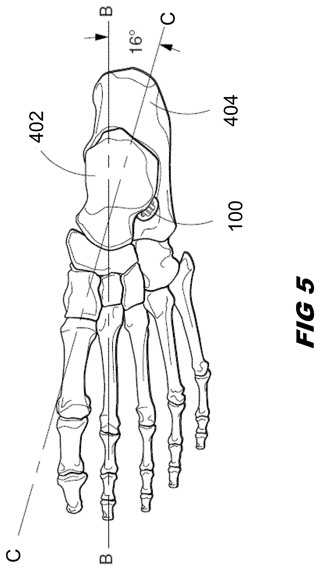
The invention is a subtalar endorphosis implant system that stabilizes the motion between the talus and calcaneus bones to insure proper foot motion. The implant is designed to maintain the natural alignment of the joint and minimize abnormal pre-operative motion. The implant surface contains ridges and channels that interact with the surrounding tissue and help maintain the implant in a proper anatomical position. The implant can be made of titanium alloy or medical grade polymer, with the option of a hole bored through its longitudinal axis for accurate placement.

Problems solved by technology

This abnormal motion will eventually lead to anatomical mal-alignment both proximally and distally.
This partial dislocation leads to excessive pronation or, more specifically, hyperpronation.
The pathomechanics of hyperpronation leads to significant deleterious effects to the bony architecture of the talus and calcaneus both proximally and distally.
Unfortunately, drilling can weaken the calcaneus and often resulted in direct or ultimate fracture.
Moreover, the stem of the implant is subject to fracture which, of course, again leads to failure of the procedure.
Also, the surgical procedures necessary for implantation is somewhat and subject to physician error.
Unfortunately, this device can only be gas sterilized.
Furthermore, it was difficult to accurately locate the device properly within the sinus tarsi.
However, this implant only corrects one portion of the deformity while both the lateral and medial portions of the sinus tarsi need correction.
Furthermore, a titanium implant is much harder than surrounding bone matter.
This can lead to bone wear and / or deformation.
Gaps in this series can lead to under and over correction.
Without any special structure to these threads, the implant can loosen and pop out of place.
The problems suggested in the preceding are not intended to be exhaustive but rather are among many which may tend to reduce the effectiveness of sinus tarsi implants known in the past.

Method used


Image

  • Sinus tarsi implant
  • Sinus tarsi implant
  • Sinus tarsi implant

Examples


Embodiment Construction

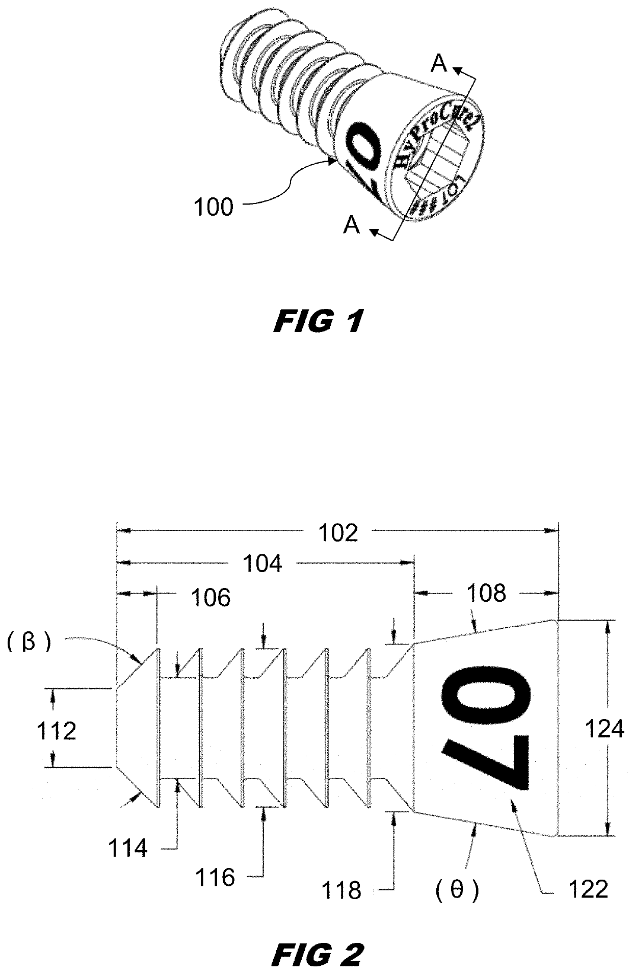
[0032]Referring now to the drawings wherein like numerals indicate the parts, FIG. 1 is a perspective view of the implant 100.

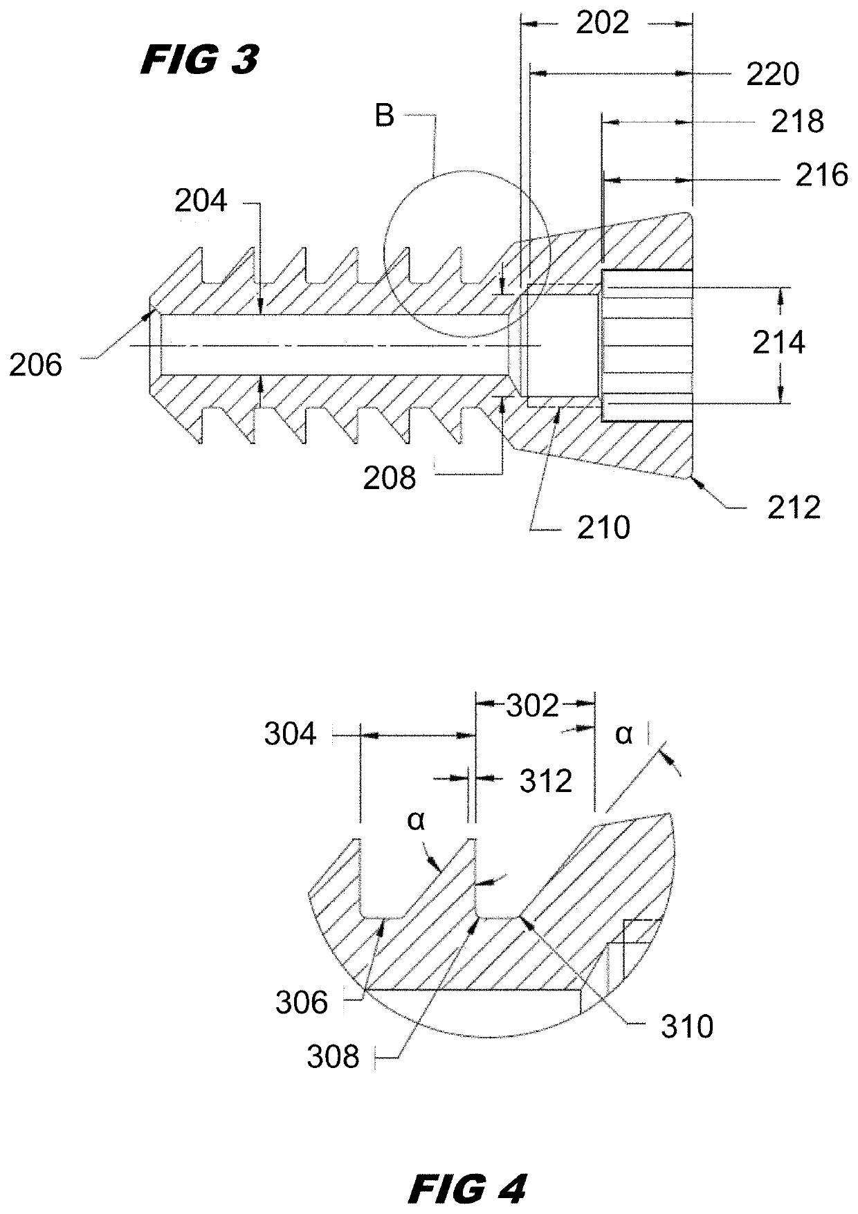
[0033]FIG. 2 depicts a side view of the implant. A preferred overall length of the implant is about 17 to 19 mm, more preferably about 18.34 mm. The implant has a cylindrical body portion 104 preferably 11 to 14 mm long, more preferably about 12.34 mm long. The implant also has a conical foot portion 122, 212. The foot has a relatively small top end 118 which is integrally connected to the cylindrical body. The foot flairs out to form a relatively larger circular base 124. Viewed from the side (FIG. 2) these two sides of the foot flair out together to form an angle, 0. This angle, 0, is preferably about 15° to 25°, or preferably each angle from 15° to 25° in 0.1° degree increments, or more preferably about 19.8°.

[0034]In order to properly block abnormal motion while allow normal motion, the implant 104 must have a carefully chosen outer diameter 116, 118, 124...


PUM


Abstract

A sinus tarsi implant for the purpose of stabilizing and restoring motion between the talus and calcaneus while allowing normal motion and alignment. In a preferred embodiment, the implant is composed of a titanium alloy that is a combination of a cylindrical portion and an axially connected conical portion. The cylindrical portion has a surface with multiple parallel grooves that are each parallel to the transverse axis of the cylinder. The grooves are uniquely shaped with a perpendicular medial side and an angled lateral side. The implant is cannulated to enable use of a guide wire that insures proper alignment during insertion.

Description

BACKGROUND OF THE INVENTION[0001]This invention relates to a medical apparatus for enhancing and for correcting skeletal mechanics. More specifically, this invention relates to the correction of certain bone alignment deformities that impair optimal biped mechanics.[0002]Excessive pronation (hyperpronation) is caused by abnormal motion between two bones of the foot; the ankle bone (talus) and the heel bone (calcaneus). This abnormal motion will eventually lead to anatomical mal-alignment both proximally and distally. The abnormal motion is due to the partial dislocation of the talus on the calcaneus resulting in the obliteration or closure of a naturally occurring space (sinus) formed between the talus and calcaneus.[0003]This sinus is referred to anatomically as the sinus tarsi. In anatomical terms, the sinus tarsi is located anterior to the posterior talocalcaneal joint and posterior to the middle and anterior talocalcaneal joint. As will be described in greater detail below, the ...

Claims


Application Information

Patent Timeline
Patent Type & Authority Applications(United States)
IPC IPC(8): A61F2/42
CPCA61F2/4202A61F2002/30224A61B17/562A61F2002/30205A61F2002/30245A61F2002/30754A61F2002/30822A61F2002/30828A61F2002/4212
Inventor GRAHAM, MICHAEL
Owner GRAHAM MICHAEL
Learn More