Stern structure of ship

A stern and ship technology, applied in the direction of ship propulsion, hull, ship construction, etc., can solve the problems of increased load and decreased propeller efficiency, and achieve the effect of reducing supporting force and suppressing cavitation.

Active Publication Date: 2011-01-12
KAWASAKI HEAVY IND LTD
View PDF2 Cites 0 Cited by
  • Summary
  • Abstract
  • Description
  • Claims
  • Application Information

AI Technical Summary

Problems solved by technology

[0002] With the increase in size and speed of ships, the load on the propeller on a single-shaft ship increases, and the efficiency of the propeller decreases

Method used


Image

  • Stern structure of ship
  • Stern structure of ship
  • Stern structure of ship

Examples


Embodiment Construction

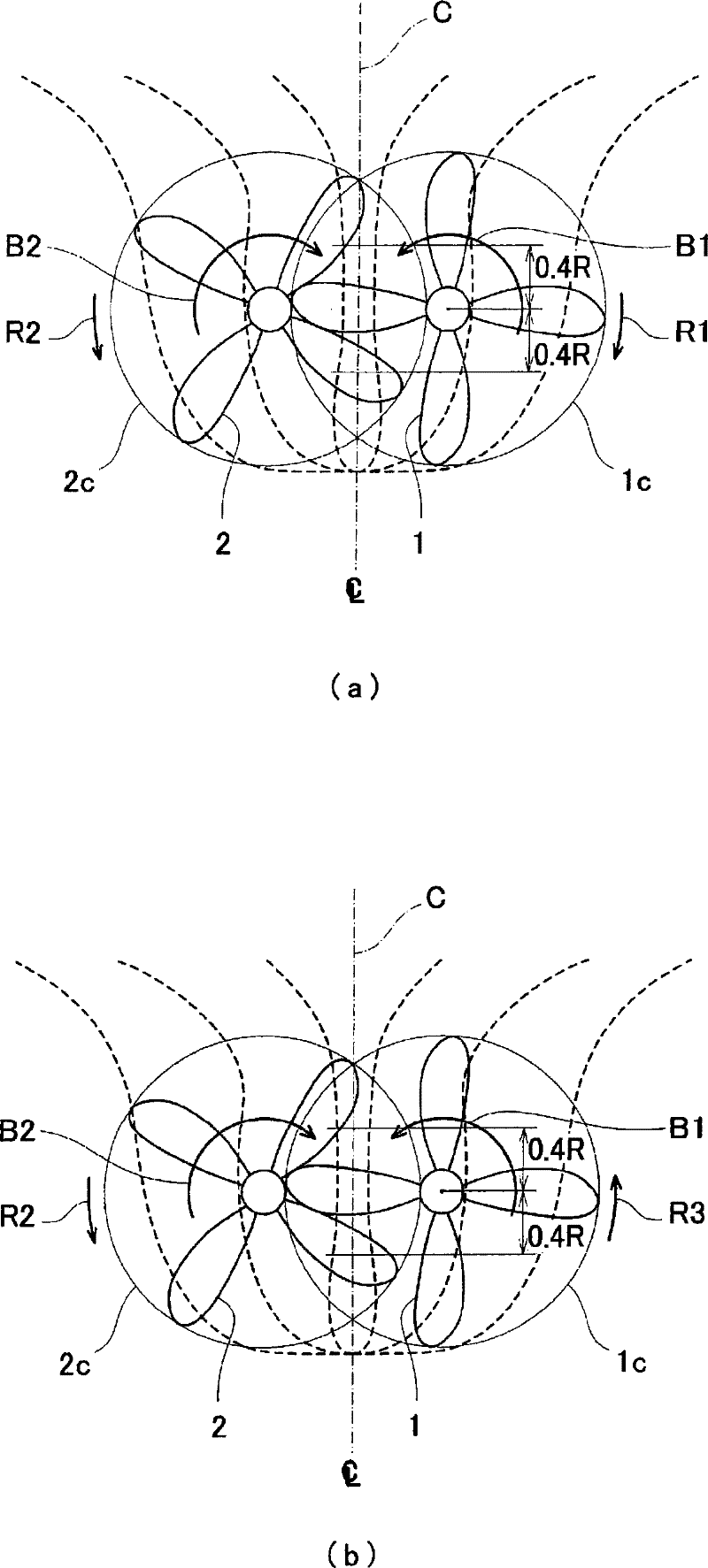
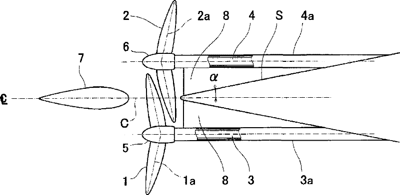
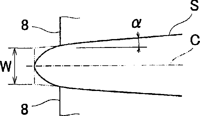
[0066] Embodiments of the present invention will be described below with reference to the drawings. figure 1 (a) and (b) are rear views of the stacked propeller viewed from the rear of the stern portion toward the front. figure 2 for its floor plan. In addition, the propellers on the left and right sides can be used no matter which one is in front. figure 2 is an example.

[0067] like figure 1 (a) and figure 2 As shown, two propellers 1 and 2 (starboard propeller 1 and port side propeller 2) that are a pair of left and right are arranged symmetrically with respect to the center line C of the hull.

[0068] The positions in the height direction of the two propellers 1 and 2 and the positions in the width direction of the hull are set so that the propeller shafts 3 and 4 of the two propellers 1 and 2 are respectively located near the centers of the left and right bilge vortexes B1 and B2. The rotation directions R1 , R2 of the propellers 1 , 2 are set to be opposite t...


PUM


Abstract

A stern structure of a ship having a uniaxial ship type stern / hull with an overlapping propeller, wherein the rear end angle a, in plan view, of the stern / hull (S) in the vertical range of at least 0.4 R (R means the radius of propeller) from the axes of the propellers (1) and (2) is set to 15 DEG or below relative to the centerline of the hull and a virtual width (on both sides of the centerline) at the tip position when the plan view is extended to the tip is set to 600 mm or shorter. Also, bracket fins (8) may be installed between stern tubes (3a) and (4a) in which propeller shafts (3) and (4) are inserted and the stern / hull (S). In addition, a wake improving fin (13) for improving wake distribution accelerated by the rotation of the forward propeller (2) and flowing into the rearward propeller (1) may be installed on the stern / hull (S) on the upstream sides of the propeller shafts (3) and (4).

Description

technical field [0001] The present invention relates to a stern structure of a ship provided with an overlapping propeller (abbreviated as OLP) for reducing the support force of the propeller and occurrence of cavitation. Background technique [0002] With the increase in size and speed of ships, the load on the propeller on a single-shaft ship increases, and the efficiency of the propeller decreases. In order to increase propeller efficiency and improve propulsion performance, there is a technology to equip two propellers. When equipped with two propellers, the load on each propeller is halved and the efficiency of the propellers is improved. In this case, it is important to avoid increasing the resistance of the hull as much as possible and not to reduce the efficiency of the hull, and double contra-rotating propellers and superimposed propellers are known as existing technologies capable of meeting these requirements. [0003] Among these, there is a superimposed propel...

Claims


Application Information

Patent Timeline
Patent Type & Authority Patents(China)
IPC IPC(8): B63H5/08B63B1/08
CPCB63B1/08Y02T70/127B63H23/34B63H5/08B63B2241/02B63B2003/425Y02T70/128B63H23/36B63B3/42B63H5/16Y02T70/10
Inventor 岩崎泰典箙一之奥村英晃
Owner KAWASAKI HEAVY IND LTD
Why Eureka
Try Eureka