Liquid ejecting apparatus and control method thereof

一种喷射装置、液体喷射头的技术,应用在打印装置、印刷等方向,能够解决喷射不良、压力室变形、气泡滞留等问题

Active Publication Date: 2011-09-14
SEIKO EPSON CORP
View PDF7 Cites 0 Cited by
  • Summary
  • Abstract
  • Description
  • Claims
  • Application Information

AI Technical Summary

Problems solved by technology

[0006] However, in a printer having a structure in which the potential of the short drive pulse and the potential of the short stop period are switched by a switch, if the difference between the potential of the short drive pulse and the potential of the short stop period is set to be large, the pressure will increase. room deformed sharply
Due to the sudden change of the pressure chamber, it is difficult to reliably suppress the cavitation caused by the negative pressure in the liquid flow path
As a result, there is a problem that bubbles generated due to cavitation remain in the liquid flow path, and ejection failure occurs due to the pressure change absorbed by the bubbles.

Method used


Image

  • Liquid ejecting apparatus and control method thereof
  • Liquid ejecting apparatus and control method thereof
  • Liquid ejecting apparatus and control method thereof

Examples


Embodiment Construction

[0025]Hereinafter, the best mode for carrying out the present invention will be described with reference to the drawings. In addition, in the embodiments described below, although various limitations were made as preferred specific examples of the present invention, the scope of the present invention is not limited to these ways. In addition, hereinafter, as the liquid ejecting device of the present invention, examples applied to figure 1 The case of the inkjet type recording apparatus (hereinafter simply referred to as a printer) is shown.

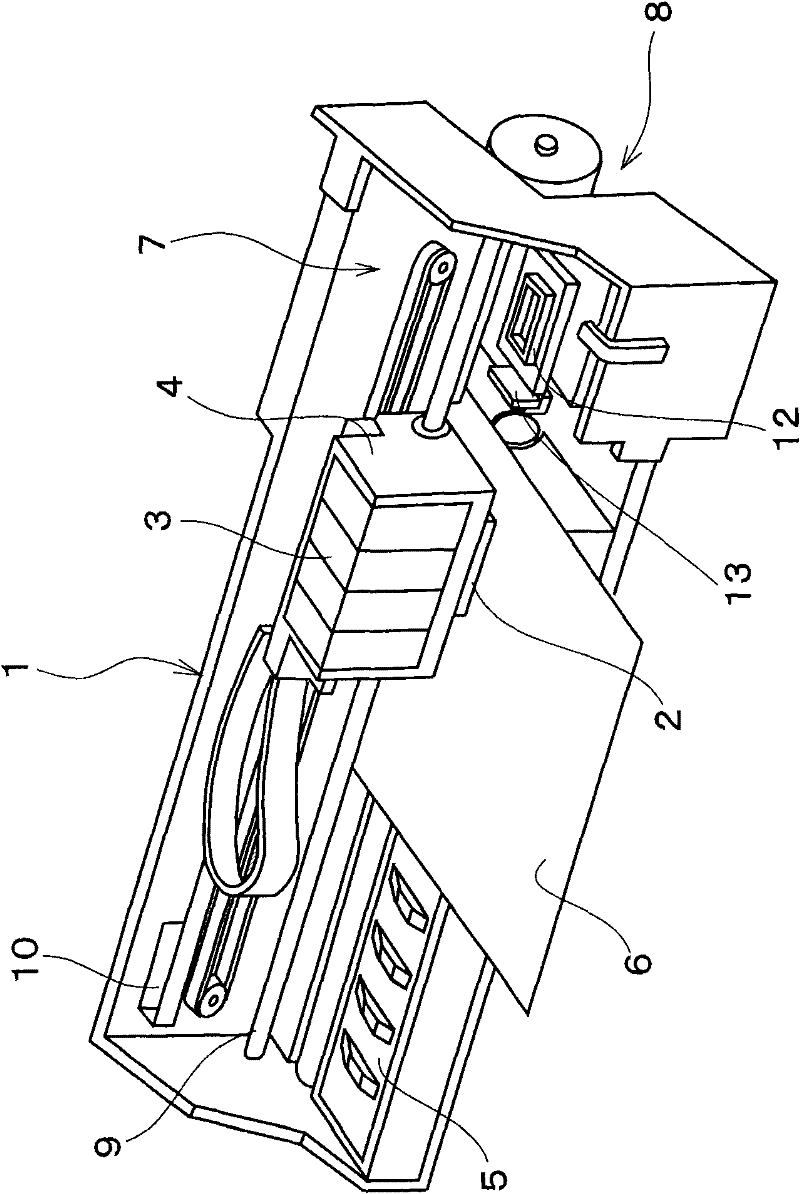
[0026] A printer 1 is schematically configured with the following components: a recording head 2 as a type of liquid ejection head is mounted and an ink cartridge 3 (a liquid in the present invention) that stores ink (a type of liquid in the present invention) can be detachably mounted. a type of cartridge), a platen 5 arranged below the recording head 2, and the carriage 4 on which the recording head 2 is mounted moves in the paper wid...


PUM


Abstract

To provide a liquid jetting device capable of preventing faulty jetting due to air bubbles by suppressing occurrence of cavitation in a liquid channel, and a method for controlling the same. A jetting driving pulse DP1 is a voltage waveform including an expansion element p1 to gently expand volume of a pressure generating chamber 21, an expansion maintaining element p2 to maintain potential VL1, a contraction element p3 to contract the volume of the pressure generating chamber 21, a contraction maintaining element p4 to maintain potential VH1, and a restoring element p5 to gently expand the volume of the pressure generating chamber 21. Time width Wd1 of the expansion element p1 is longer than time width Wh1 of the expansion maintaining element p2, and time width Wd2 of the restoring element p5 is longer than time width Wh2 of the contraction maintaining element p4, then first reference potential VB1 is set to be equal to or above 50% of the potential VH1 of the contraction maintainingelement p4. By applying the jetting driving pulse DP1 to a piezoelectric vibrator 26, flow velocity of ink jetted from a nozzle opening 28 is 0.36 mg / s or more.

Description

technical field [0001] The present invention relates to a liquid ejecting device including a liquid ejecting head such as an ink jet recording head and a control method thereof. Background technique [0002] A liquid ejecting device is a device that includes a liquid ejecting head capable of ejecting a liquid, and ejects various liquids from the liquid ejecting head. As a representative device of the liquid ejecting device, for example, an image recording device such as an ink jet printer (hereinafter simply referred to as a printer) equipped with an ink jet recording head (hereinafter referred to as a printer) as a liquid ejecting head can be mentioned. , simply referred to as a recording head), images and the like are recorded by ejecting and landing droplet-shaped ink from nozzles of the recording head on a recording medium (ejection object) such as recording paper. In addition, in recent years, it has been applied not only to this image recording device but also to vari...

Claims


Application Information

Patent Timeline
Patent Type & Authority Applications(China)
IPC IPC(8): B41J2/045B41J29/393
CPCB41J2/04573B41J2/04581B41J2/04588
Inventor 金子智重
Owner SEIKO EPSON CORP
Why Eureka
Try Eureka